JIG ASSEMBLY, MOUNTING, AND USING THE CLAMPS
2
Chapter 1 D4R Pro User Guide
3
5
/16"[84mm]
6"[150mm]+
29
5
/
16
"[745mm]
37"[940mm]+
1"[25.4mm]
1
2
4
3
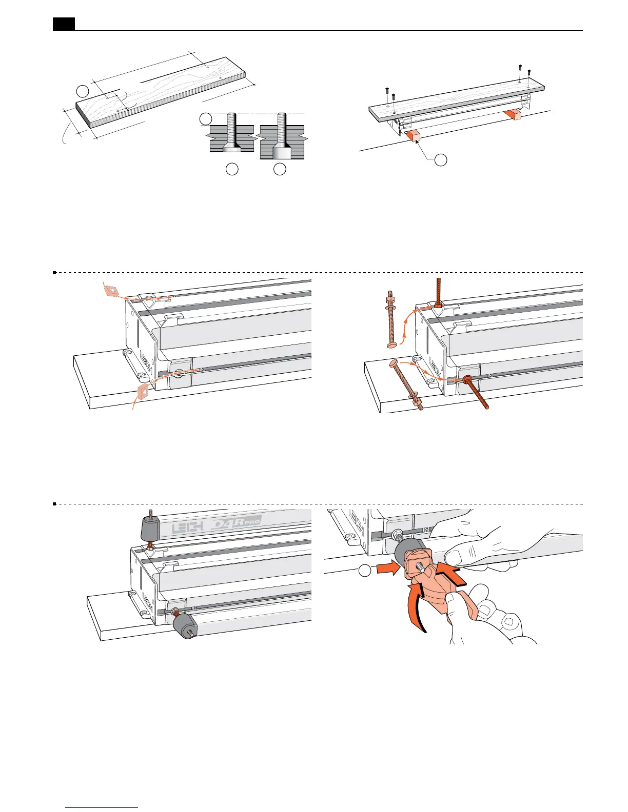
1-1 Prepare a flat board at least
3
⁄4"[20mm] thick, and a mini-
mum of 37"x6"[940x150mm]. Drill four
9
⁄32"[7mm] holes on
29
5
⁄16"x 3
5
⁄16"[745x84,2mm] centers, 1"[25.4mm] in from the
front edge of the board
➀
. Countersink
➁
or counterbore the
underside
➂
if the board is thicker, so that the four
1
⁄4-20x1" long
machine screws will project above the top surface by
3
⁄8"[9,5mm]
➃
.
1-2 Turn the jig body upside-down on two blocks
➀
(to protect
the side stops). Using the four nuts and four countersunk machine
screws, bolt the base board to the jig using the two nut recesses in
each end housing. Holes drilled 1"[24mm] from the front edge
of the board go to the front of the jig. Now you can clamp your
D4R to any bench.
1
1-3 With the jig right side up, insert one square nut (part #284)
into each of the channels in the main extrusion. These nuts are
for possible future attachment of accessories. See Chapter 9.
1-4 Insert the four clamp T-bolts into the T-slots (two at each
end of the jig). Position so that the washers seat into the round
milled recesses. Tighten the four clamp bolt nuts with the Leigh
wrench.
1-5 Place four springs and two clamp bars on the T-bolts.
Make sure the clamp bars move freely on the T-bolts.
1-6 Place one black step washer
➀
on each T-bolt with the
flat side against the clamp bar. Screw a clamp lever assembly onto
each T-bolt, making sure the cam lobes are between the step
washer sidewalls.
1