THROUGH DOVETAILS
22
Chapter 8 D4R Pro User Guide
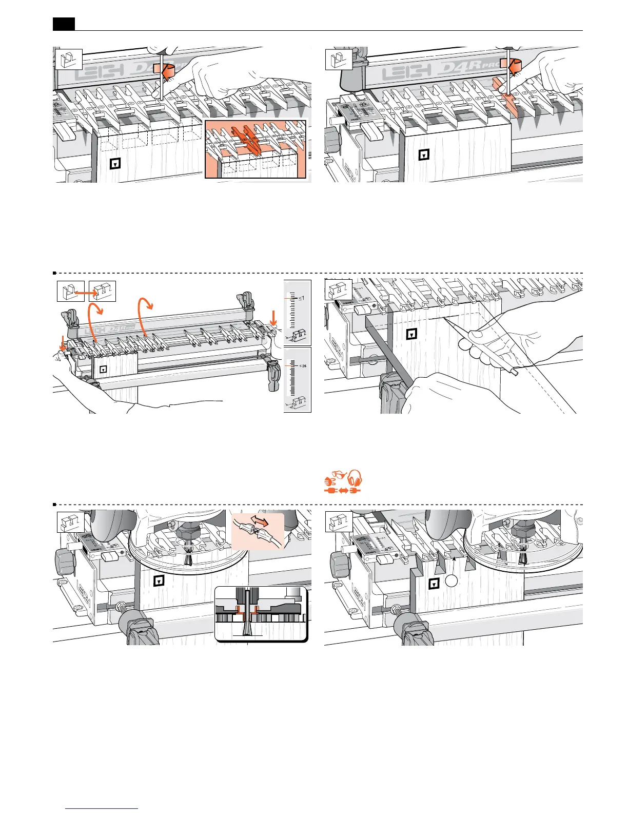
8-16 Place the end of a pin board horizontally flush under the
guidefingers and mark a thin pencil line partly across the tail
board.
REMEMBER SAFETY!
8-17 Place the router on the finger assembly and adjust the router
until the dovetail bit tip is level with the center of the pencil line.
Note: This means the pin socket will be half a thin pencil line deeper
than the thickness of the pin board, leaving minimal cleanup after
assembly. Check to make sure the bit rotates freely.
8-18 Before routing the tails, read “Hints and Tips 17-10". Plug in
the router and rout out the half-pin and pin sockets. Use only light
side pressure on the guide fingers. Take care not to rout unwanted
sockets where there are gaps between the pairs of fingers
➀
. Rout
only between the rounded guidefinger tips. See Hints and Tips
17-20.
1
8-13 Space and lock the three remaining pairs as shown. Again,
judge it by eye. If it looks right on the jig, the finished joint will
look right. Note: Here we have shown pins of equal width, but
with tails of increasing width. However, by opening up a pair of
guides, the pin (and pin socket) can be widened for decorative or
structural reasons as shown in the drawing inset.
8-14 Tighten any other loose guidefingers.
8-15 Rotate the finger assembly to the
D
TD TAILS mode, and
set it to the ≤1"[≤26mm] position on the scale. Lower the finger
assembly onto the spacer board. All TD tails are routed at this
≤1"[≤26mm] setting. (The ≤1" setting allows the dovetail bit
to pass completely through all tail boards.)
 Loading...

