CONTENTS AND STANDARDS
iv
D4R Pro User Guide
Glossary of Symbols
To help you understand the instructions and illustrations in this
manual, we have used a number of international symbols, plus
a few special ones of our own. They are all explained below. You
needn’t worry about memorizing these symbols now, because
they are repeated quite frequently in this user guide, and you
will soon get used to them.
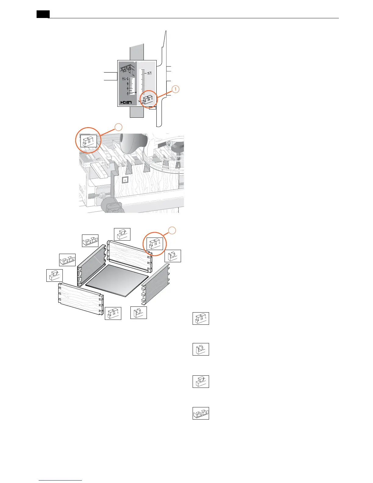
The Leigh jig’s guidefinger assembly can be in any one of four
joint modes, depending on what type of joint and which part
of the joint you are routing. Each finger assembly scale has it’s
own mode icon
➀
, identifying the joint part being routed. You
will also find the joint mode icon in the top left corner of most
illustrations
➁
, indicating which finger assembly mode to use.
Sometimes a joint mode icon will be used to identify a board
➂
.
These are the four joint mode icons:
TD Tails
(tails for through dovetail joints)
TD Pins
(pins for through dovetail joints)
HB Tails
(tails for half-blind dovetail joints)
HB Pins
(pins for half-blind dovetail joints)
2
3