VARIABLY SPACED HALF-BLIND DOVETAILS
34
Chapter 10 D4R Pro User Guide
10-8 Routing a Test Joint Use the Leigh e7-Bush, and No.120-
8,
1
⁄2"[12,7mm] 14° dovetail bit. Select several pieces of
3
⁄4"x
5
1
⁄2"[20 x 140mm] x about 8"[200mm], and the plastic bridge
extrusion. Note: Half-blind pin boards must be minimum
1
⁄2"(13mm)
thick to clamp. For thinner boards see fig.10-21.
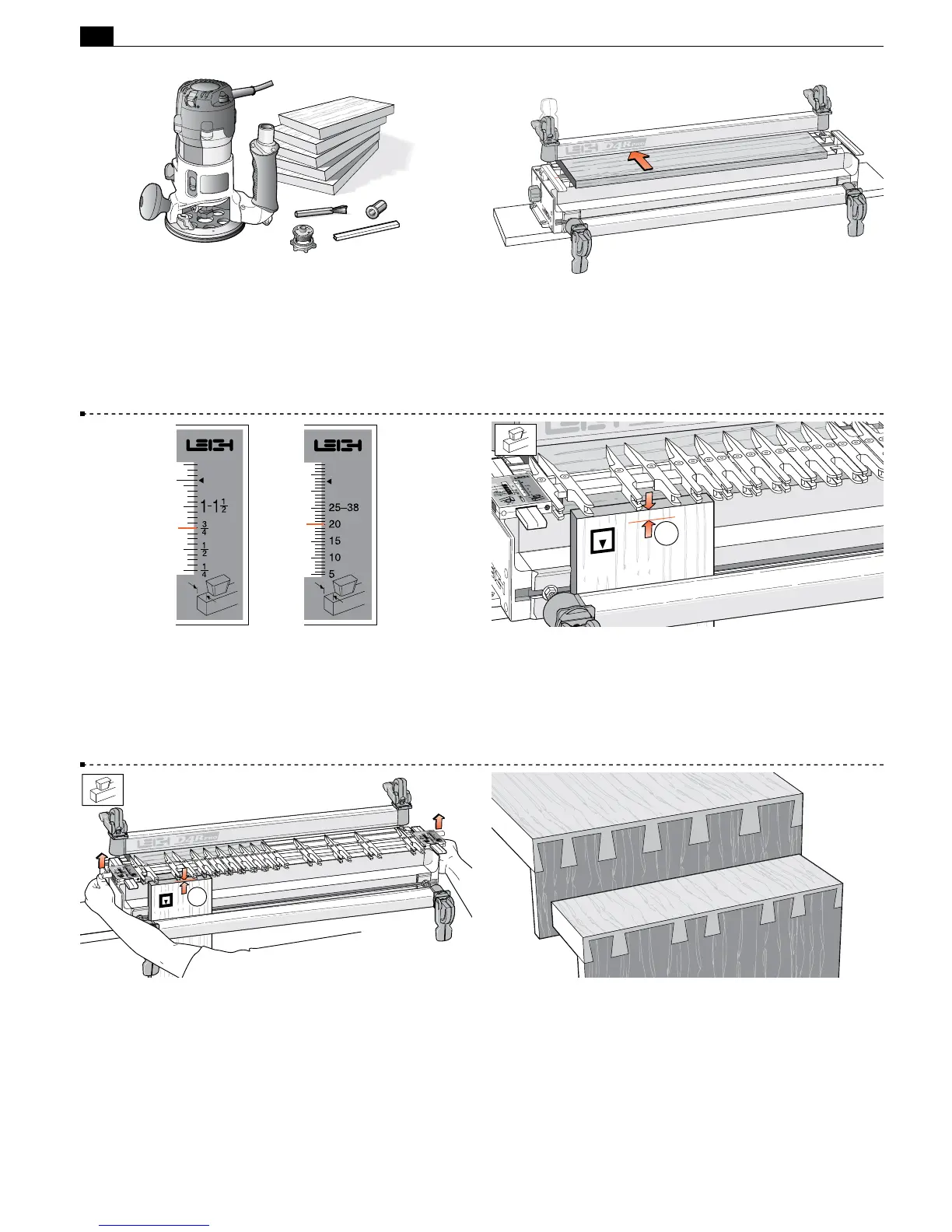
10-9 Clamp the spacer board in the rear clamp.
10-10 Mount the finger assembly on the support brackets in
the
H
HB TAILS mode, flat on the spacer board, scales set on the
thickness of the tail board (
3
⁄4 "[20mm] in this instance).
The
H
HB TAILS scale is always set at the tail board thickness.
The scale increments above 1-1
1
⁄2"[25- 38mm] are for use on
sliding dovetails (see Chapter 16).
10-11 Measure and mark a line on the inside face of the tail
board
➀
to the working depth of the bit to be used as per 10-2
of this chapter. Clamp this test tail board in the left front clamp,
against the side stop with the top edge flush under the guidefingers,
and the inside face
i
of the drawer side away from the jig.
1
10-12 Unlock and raise the finger assembly support brackets
slightly so that the finger assembly is about
1
⁄8"[2mm]
➀
above
the boards. This will allow easy movement of the guidefingers.
1
10-13 While typical traditional layouts have symmetrical pins and
spacing with half-pins at each edge, the Leigh jig allows infinitely
variable joint designs. Different thickness boards can be easily
joined together. Pins can be various sizes and randomly spaced to
suit just about any design you create. Before attempting joints of
asymmetrical design, see Chapter 14.