SINGLE PASS HALF-BLIND DOVETAILS
42
Chapter 11 D4R Pro User Guide
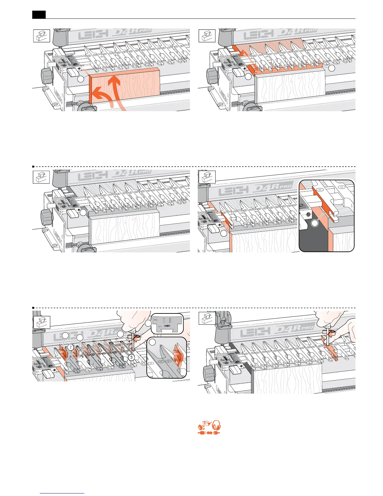
11-9 With the finger assembly raised in the
H
HB Tails mode,
clamp a drawer side in the front left side, against the side stop and
the top end edge slightly above the jig body top
➀
.
Note: Drawer side (tail board) thickness can be from
7
⁄16" to
9
⁄16"[11mm to 14mm]. See 11-25 re drawer side thickness greater
than 9/16".
1
1
1
11-11 With the scale set on
1
⁄2"[12,7mm], lower the finger assem-
bly to about
1
⁄8"[3mm] above the drawer front to ease adjusting the
guide fingers
➀
. The scale is always set on the 1/2"[12,7mm]
mark for single pass dovetails.
1
11-12 With boards the same width as a board width chart size
(Fig. 11-8), set the first guide finger flush against the board edge
➀
and tighten. If board width is greater than a chart size, set the first
finger in from the edge by half the additional board width
➁
. If
board width is narrower than a chart size, overhang the first finger
by half the difference and tighten.
2
1
11-13 Set the dovetail spacer
➀
with numeral 2 facing right, against the
single left guide finger. Move the next finger pair
➁
against the spacer
and tighten. There will be a gap between the pointed ends (pin end) of
the fingers, not the tail end. Remove and locate the spacer to the right of
the tightened fingers. You should feel friction when removing the spacer
➂
.
Slide next finger pair
➃
against spacer and tighten. Repeat across the
board width to position
➄
plus one more finger pair. Place the spacer
against the last finger pair
➅
and add one more half finger to the right.
3
1
1
4
2
5
6
11-14 Move any spare fingers so that they will support the router
and tighten all loose fingers.
Lower the assembly flat onto the drawer front.
REMEMBER SAFETY!
11-10 Place a sample drawer front from
5
⁄8" to 1
1
⁄2" thickness
[16 to 38mm] in the rear clamp. Clamp with the side edge against
the left rear side stop, front end edge touching flush across the rear
of the front board
➀
. Note: the
5
⁄8" [16mm] minimum thickness
can be reduced if using other shallower bit depths. ! Board edges
must be square.
 Loading...

