BOX JOINTS
58
Chapter 15 D4R Pro User Guide
15-19 3⁄4"[19mm] Box Joints Set-up and space the guide
fingers exactly as for
3
⁄8"[9mm] joints. Start with the same e7-Bush
setting. See 15-2 thru 15-9.
Prepare four boards using the board width chart for
3
⁄4"[19mm]
joints and number them 1 to 4 around the box
➀
with the com-
mon edges marked.
4
4
3
3
2
2
1
1
1
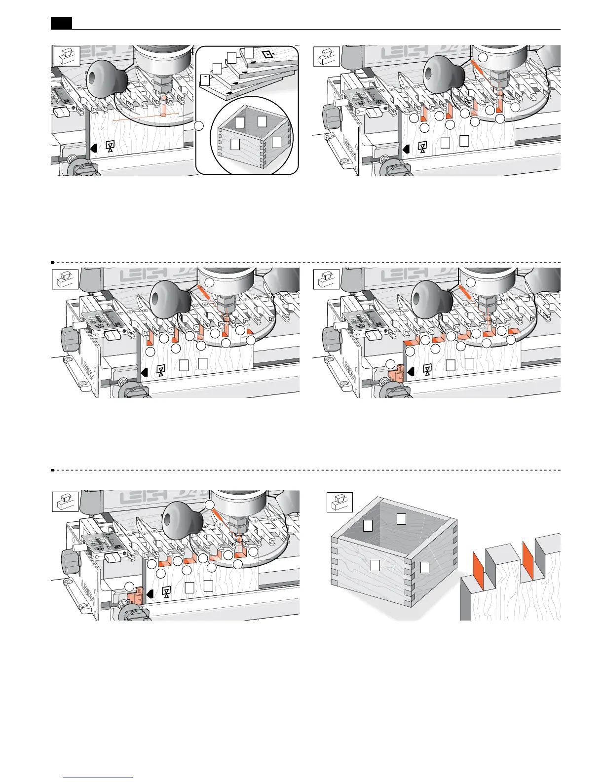
15-20 Rout both ends of boards 1 and 3 but only rout between
the guide finger openings
➀
not between the finger sides
➁
. Keep
the common edge against the side stop.
Hint: Mark the router base at the 12 o’clock position
➂
and steer
this mark along the pointed ends of the fingers at the rear of the
assembly.
3
1
2
2
2
2
2
1
1
1
3
1
15-21 Now rout both ends of boards 2 and 4, with the common
edge against the side stop but only rout between the finger sides
➁
not between the finger openings
➀
.
Hint: Now steer the base 12 o’clock mark between the pairs of
finger points
➂
.
2
2
2
2
3
2
1
1
1
1
4
2
15-22 Remove the board and fit the Spacer to the side stop with
number 3 showing
➃
. Now rout both ends of boards 2 and 4 again,
with the common edge against the Spacer and again …only rout
between the finger sides
➁
, not between the finger openings
➀
,
steering the router mark between the pairs of finger points
➂
.
3
4
4
2
2
2
2
2
2
1
1
1
1
15-23 With the Spacer still in position rout both ends of boards
1 and 3, with the common edge against the Spacer and only rout
between the finger openings
➀
, steering the router mark along
the finger points
➂
.
3
4
3
1
2
2
2
2
2
1
1
1
1
15-24 Joint fit Check for joint fit as usual, and repeat testing
if required. Theoretically, there will be nothing in the
3
⁄4"[19mm]
sockets, literally a zero thickness wall, where the bit has passed by
twice. However, routing tolerances can leave a very thin “wall”
uncleared by routing. This can be quickly removed with a chisel
or sandpaper.
■
1
2
3
4
 Loading...

