45
45
RTJ400 User Guide
Chapter 10
Box Joint Procedures - 3/8"
A
B
A
A
A
C
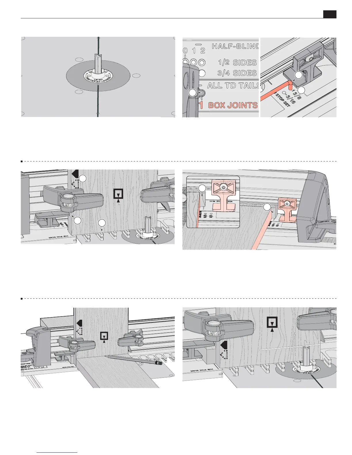
10-9 Insert the right frame pin in the
No.1 BOX JOINTS
hole
A
and the left frame pin in the
HALF-BLIND & BJ
slot. Latch the
frame. Put the short end of the stop rod into the
3/8" BJ STOP SET
hole
B
. Slide the sidestop to lightly touch the rod
C
and tighten
the sidestop. Store the stop rod in the ¾" slot.
10-12 Place the end of a socket board on the template and
pencil a line on the pin board.
10-13 Adjust the bit to the center of the pencil line. Double
check that the bit still rotates freely.
IMPORTANT: Bit height
determines the flushness of the joint, so set your bit properly
the first time.
Adjustments for flushness are at the end of the
chapter.
10-8 With the router unplugged, install the supplied ⅜" Leigh
143-500 bit. For cleaner routing use the optional ⅜" Leigh
173-500 (HSS) or 173-500C (solid carbide) spiral upcut bit,
available at leighjigs.com.
Make sure the bit spins freely before
connecting the power.
10-11 Position a backer board " [1.5mm] away from the
edge of the pin board
A
. This prevents the backer board from
interfering with the sidestop when the frame is repositioned in
the second step. The backer board stays in place for the complete
procedure.
Note: Clamp removed for clarity.
10-10 Clamp pin board 1 flush on the template
A
with the side
edge against the sidestop
B
.
Always keep the same side edge
of the board to the sidestop when routing box joints
C
.
If the
board width is only slightly narrower than the chart width, center
the board over the template, clamp in place and move the sidestop
against the board.
C
B