67
67
RTJ400 User Guide
Chapter 13
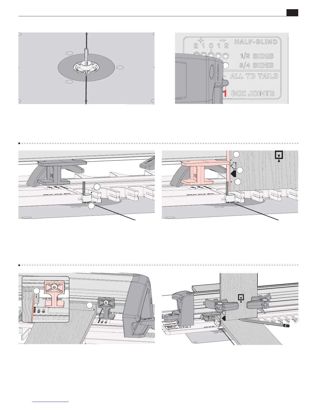
Box Joint Procedures - 3/32"
A
A
C
13-10 Raise the bit above the template and move the template,
putting the eBush in the first template opening
A
with the inner
edge of the opening
B
touching the bushing.
13-9
Insert the right frame pin in the
No.1 BOX JOINTS
hole and
the left frame pin in the
TD TAILS & BJ
slot and latch the frame.
13-11
Set pin board 1 on the template, touching the " bit
A
.
Clamp in place. Move the sidestop to touch the board edge
B
and tighten it.
The
⁄"
box joint requires moving the template
from right to left in four steps.
Always keep the same side
edge of the board to the sidestop when routing box joints
C
.
13-8 With the power disconnected from the router, install the
optional " Leigh 163 bit. Make sure the bit spins freely
within the bushing before reconnecting the power.
13-13 Place the end of a socket board on the template and
pencil a line on the pin board.
13-12
Position a backer board at least " [4.5mm] from the
board edge
A
. This prevents the backer board from interfering
with the sidestop when the frame is repositioned in subsequent
steps. The backer board stays in place for the complete procedure.
Note: Clamp removed for clarity.
A
B
B
A