11
Berlin, Venice: Assembly and adjustment of quill‐type handle‐stem:
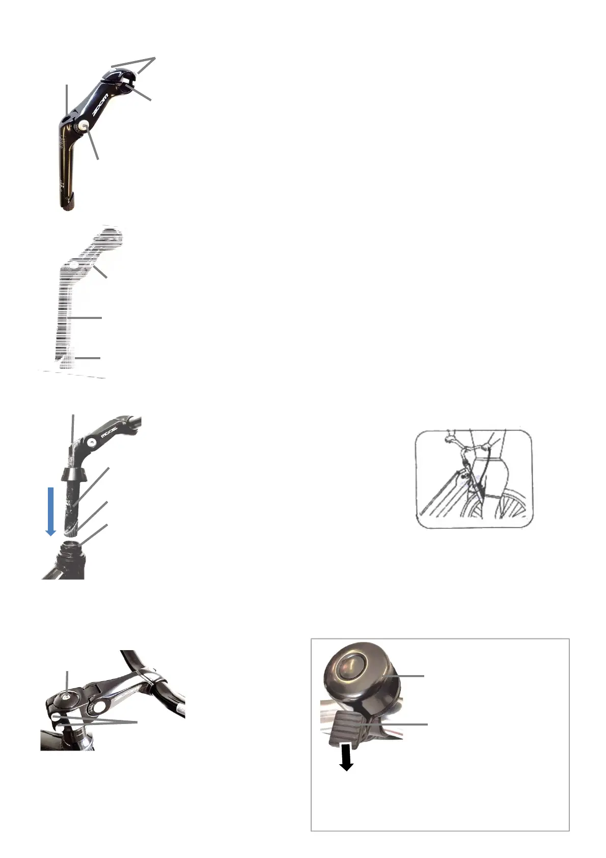
Figure QS1: view from top/side
Handlebar
clamp bolts
Insert handle‐
bar here
Hinge bolts
(do not
loosen!)
Attachment
bolt
Wedge‐nut
Figure QS2: view from bottom/side
Angle adjustment bolt
Located UNDERNEATH
Handle‐stem
Figure QS1‐3: Parts of the quill‐type
handle‐stem.
• Installation of stem: Insert wedge‐nut
and handle‐stem into head tube of
bicycle frame (Figure QS3). If wedge‐
nut does not fit into frame, loosen
attachment bolt by several turns anti‐
clockwise and try again. Push stem
down in direction of arrow shown.
Make sure minimum insertion mark on
handle‐stem is not visible after stem is
installed. Tighten attachment bolt to
14 Nm.
• To insert handle‐bar into stem,
remove handlebar clamp bolts, insert
handle‐bar at location shown in figure
QS1. Centre handle‐bar, adjust
position until suitable and tighten
handle‐bar clamp bolts to 19Nm.
• To adjust ANGLE of HANDLEBARS,
loosen handlebar clamp bolts, adjust
handle‐bar angle and tighten handle‐
bar clamp bolts to 19 Nm.
• To adjust ANGLE of STEM loosen angle
adjustment bolt (Figure QS2)
underneath handle‐stem. DO NOT
loosen hinge bolts (Figure QS1).
Tighten angle adjustment bolt to 19
Nm.
• To adjust HEIGHT of stem loosen
attachment bolt and raise handle‐
stem. Always make sure minimum
insertion mark on handle‐stem is not
visible after stem is installed and that
at least 2¾“ (70mm) of stem are inside
frame. Tighten attachment bolt to 14
Nm.
WARNING: If quill stem is too high and
minimum insertion mark is visible the bike
can be damaged, you may loose control
and fall.
WARNING: If bolts are overtightened or
under‐tightened components may break
and cause you to fall.
Head tube
of bicycle
frame
Attachment bolt
Wedge‐nut
Minimum
insertion
mark
Figure QS3
Handle‐stem
Figure QS4: To align stem
with wheel, walk to front of
bike, put wheel between your
legs. Adjust position until
stem is centered. Loosen
attachment bolt (Figure QS1)
if needed and tighten to 14
Nm after adjusting. Move
handle‐bar left and right
while holding wheel between
your legs. The alignment
shouldn’t come loose easily.
Make sure handle‐stem is
installed safely and push
down handle‐bar down with
forcetomakesureitwon’t
come loose while riding. If
needed tighten handle‐bar
clamp bolts and handle‐bar
attachment bolts. (Figure
QS1‐3).
WARNING: If handle‐stem
and handle‐bar are not
installed correctly they may
become loose during riding
andcauseyoutofall.Check
safe installation before every
ride!
FigureQS4
Figure BE1: Bell.
The bell is attached to
thehandlebarwitha
clamp and a bolt. Push
the trigger down by
tapping it with your
finger briefly in the
direction of the arrow
and release it to ring
the bell.
Bell
Trigger
CrossX: Assembly and adjustment
of direct‐connect handle‐stem
:
Figure DS1: The steerer clamp bolts (1) attach the stem to the
bike. To adjust the alignment of the stem with the front wheel,
loosen steerer clamp bolts (1) and tighten after alignment to
13 Nm. Make sure the centre bolt (2) is tight (13 Nm). Direct
connect stems cannot be adjusted in height.
To install handle‐bar, adjust the angle of the handle‐stem and
alignment refer to figures QS1‐4.
1
2
Use the bell to make other people aware of you in traffic,
e.g. before passing a pedestrian. Make sure the bell is
functional and securely installed.
Bell
©LeitnerPtyLtd2019