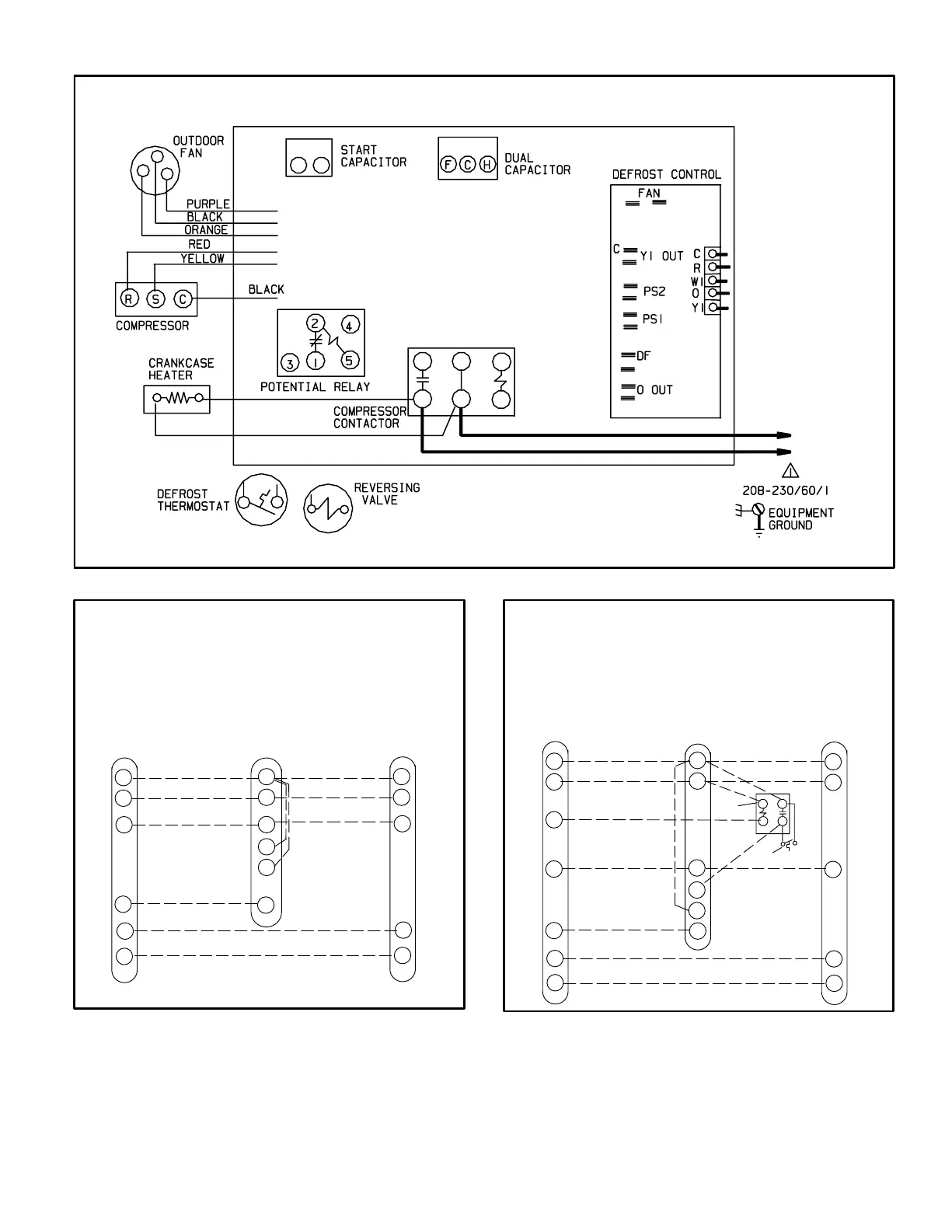
Page 5
Typical Wiring Field Wiring Diagram
Figure 4
*
*
* may be optional
R
C
W1
Y1
O
G
R
C
W1
W2
W3
G
reversing valve
12HPB and Blower Unit
Thermostat Designations
(Some connections may not apply.
Refer to specific thermostat and indoor unit.)
Thermostat
Indoor
Unit
R
C
W1
Y1
O
Outdoor
Unit
power
power
common common
1st. stage aux. heat
1st. stage aux. heat
indoor blower
compressor
Figure 5
R
C
W1
Y1
O
G
R
C
W1
W2
W3
G
Outdoor Unit and Blower Unit
Thermostat Designations
(with emergency heat)
(Some connections may not apply.
Refer to specific thermostat and indoor unit.)
Thermostat
Indoor
Unit
Outdoor
Unit
E
R
C
W1
Y1
O
reversing valve
indoor blower
compressor
power
power
common common
1st. stage aux. heat
1st. stage aux. heat
emergency heat
em.
heat rly
outdoor t’stat
Figure 6
 Loading...


