0906-E
47
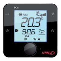
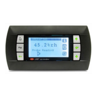
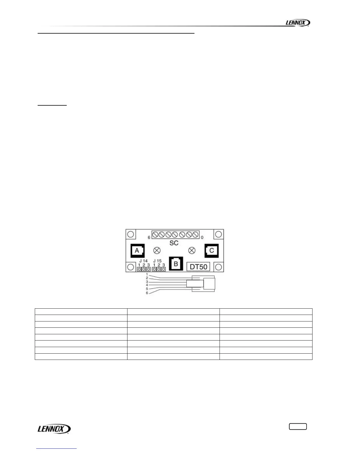
Terminal connection board installation guide DT 50
The board is fitted with three "telephone" RJ12 plugs. Ensure the board is correctly connected.
Standard connection is:
• Climatic on connector C
• Unit DC50 on connector A
• Remote DC50 on connector SC
• DS50 on connector B
Jumpers:
"Displays" are supplied directly by the Climatic board with 30Vdc. Take particular care at the path this 30V is
taking when several boards are being used.
J14 and J15 can switch on or off the direct current from the power supply:
J14 and J15 set between1-2
Connectors A, B, C and screw connector SC are in parallel. Power supply available to all connectors.
J14 and J15 set between2-3
Connectors B and C are in parallel but line 1 and 6 don't reach connector A and screw connector SC.
"Displays" connected to these ports will not be powered.
If J14 and J15 are set in different positions the "terminal connection board" DT50 DOES NOT WORK.
NOTE:
When a shielded wire is used the metallic case of the "Terminal connection box" DT50 must be earthed.
RJ12 PIN connection
SC Terminals RJ12 Pin conn Description
0 + shield / earth
1 1 +VRL=30V
2 2 GND
3 3 Rx- / Tx-
4 4 Rx+ / Tx+
5 5 GND
6 6 +VRL=30V
 Loading...