-00
80
CLIMATIC CARD ØØ KP01
¸ Supply
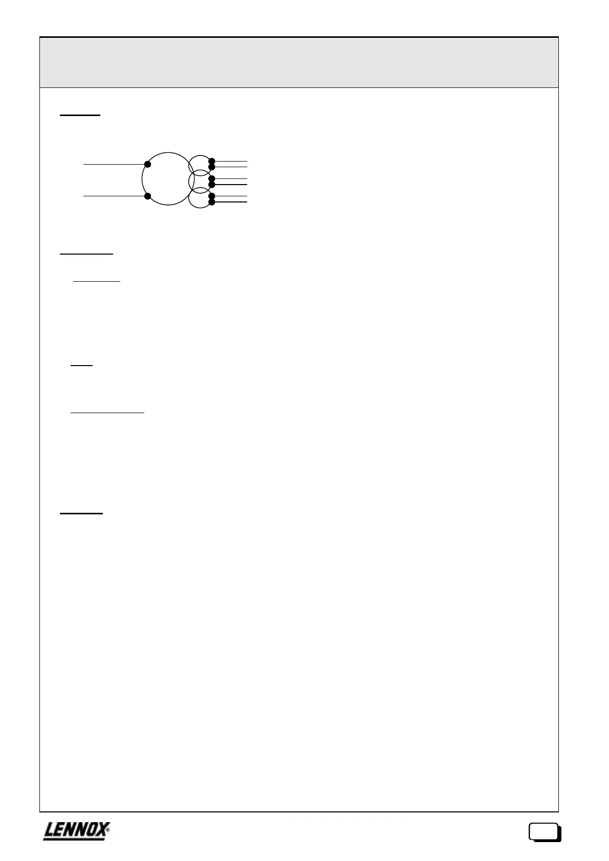
A single transformer provides the power supply to the Climatic and its extensions :
¹ Switches
F SW2,SW3 :
By default, the card is configured in
If there is a link between cards (maximum 8), set switches as follows:
• Card 0 (master) internal supply: SW2 and SW3 = 1-2
• Card n (slave) external supply: SW2 and SW3 = 2-3 (card 0 supplies the link)
F SW4 :
This switch turns the battery on or off.
Caution: the dater will not work if the battery is not in position "on".
F SW5-1 à SW5-8 :
These switches are used to configure the type of analogue input (CTN / 0-20mA / 0-5V).
Caution: every addition of a KP05 extension (1 to 3) causes an analogue input (1 to 3) on the main KP01
unit to become unavailable. In this case, the switches for the corresponding inputs (SW5-1 to SW5-3)
must be set to "inactive", i.e. neither on position CTN, nor on 0-20mA, but simply withdrawn.
º Bus I²C
Never handle the I²C bus when the power is switched on.
230Vac
12V/6VA for supply to KP07VDU console
12V/7.2VA for isolated supply to extensions KP03/KP04/KP01
12V/50VA for KP01 supply
 Loading...

