-00
83
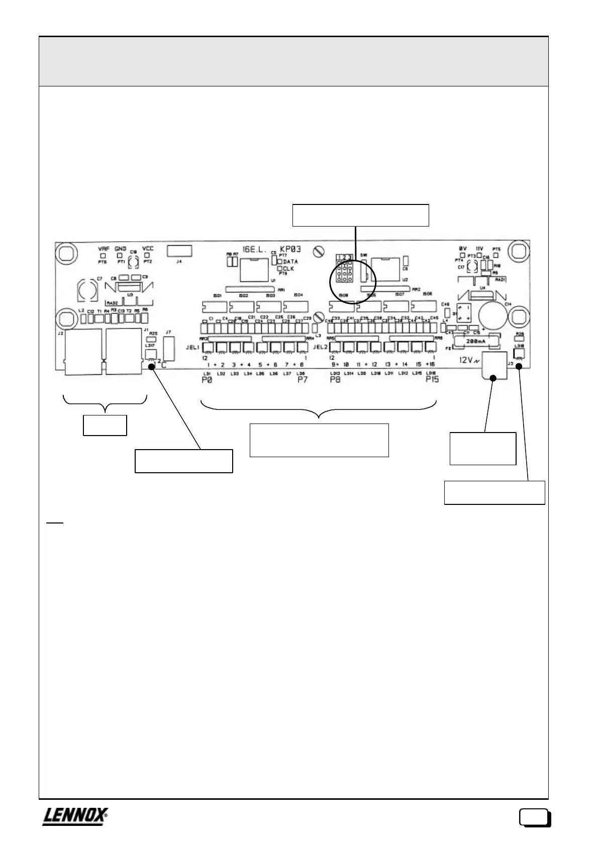
EXTENSION 16 ENTREES LOGIQUES ØØ KP03
The KP03 card is used for processing the 16 logic inputs (10V/10mA).
It is possible to connect up to 3 extensions to a KP01 card, to attain a maximum capacity of 8 +3 x 16 = 56
logic inputs.
The state of each input is shown by an LED.
Key :
J1, J2: RJ45 connectors for I²C Bus
J3: 2 point removal pin connector, pitch 5.08 for 12Vac external supply
JEL1, JEL2: 12 point removal pin connectors, pitch 3.81 for logic inputs
J4, J7: Locations for connection to earth using FASTON 6.35 earth lugs
LD1, LD16: LED status of 16 inputs
LD17: LED presence of power from KP01
LD18: LED presence of 12Vac isolated power
SW1: Switch for the configuration of the card address
The position of jumpers for each configuration is marked on the card.
PT1: Earth
PT2: Vcc1 (+5V)
PT3: Vcc2 (+11V isolated)
PT4: 0V isolated
PT5: +12V rectified and filtered (before regulation)
PT6: VRF
PT7: SDA/I²C signal (DATA)
PT8: SCL/I²C signal (CLOCK)
Led power on
12Vac
isolated
Led power on
Logic inputs 1 to 16 (+)
common to all inputs
Addressing configuration
I²C Bus
 Loading...

