Page 27
TABLE 11
Unit
High Altitude Pressure Switch
4501 - 7500 ft
Natuarl LP/Propane
-040 20K91 N/A
-060 No Change No Change
-080 No Change N/A
-100 20K91 N/A
Other Unit Adjustments
Primary Limit
The primary limit is located on the heating compartment
vestibule panel. The secondary limits (if equipped) are lo-
cated in the blower compartment, attached to the back
side of the blower. These auto reset limits are factory-set
and require no adjustment.
Thermal Switch
These manually reset switches are located on the front of
the box.
Pressure Switch
The pressure switch is located in the heating compartment
adjacent to the combustion air inducer. The switch checks
for proper combustion air inducer operation before allow-
ing ignition trial. The switch is factory-set and requires no
adjustment.
Temperature Rise
After the furnace has been started, and supply and return
air temperatures have been allowed to stabilize, check the
temperature rise. If necessary, adjust the blower speed to
maintain the temperature rise within the range shown on
the unit nameplate. See TABLE 11 for allowable heating
speeds.Increase the blower speed to decrease the tem-
perature. Decrease the blower speed to increase the tem-
perature rise. Failure to adjust the temperature rise may
cause erratic limit operation.
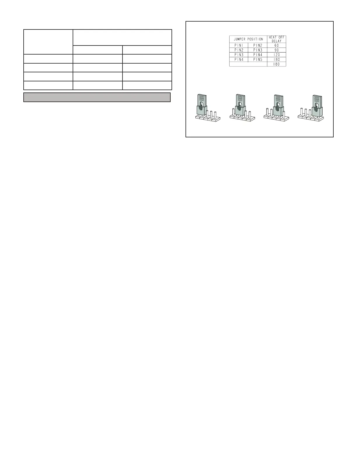
Fan Control
The heat fan-on time of 30 seconds is not adjustable. The
heat fan-o delay (amount of time that the blower oper-
ates after the heat demand has been satised) may be
adjusted by changing the jumper position across the ve
pins on the integrated control. The unit is shipped with a
factory fan-o delay setting of 90 seconds. The fan-o de-
lay aects comfort and is adjustable to satisfy individual
applications. Adjust the fan-o delay to achieve a supply
air temperature between 90° and 110°F at the moment
that the blower is de-energized. Longer o delay settings
provide lower return air temperatures; shorter settings
provide higher return air temperatures. See FIGURE 26.
Constant Torque Motor
EL180UHNE units are equipped with a constant torque
ECM motor. It has a DC motor coupled to an electronic
control module both contained in the same motor hous-
ing. The motor is programmed to provide constant torque
at each of the ve selectable speeds. The motor has ve
speed taps. Each tap requires 24 volts to energize.
HEAT FAN‐OFF TIME IN SECONDS
To adjust fan-off timing, reposition jumper across pins to
achieve desired setting.
NO JUMPER
60
90
120
180
60
90
120
180
60
90
120
180
60
90
120
180
60 Second
off Time
90 Second
off Time
120 Second
off Time
180 Second
off Time
FIGURE 26
Input Voltage Requirements
The circuit is designed to be operated with AC voltage. A
voltage of 12 to 33VAC is required to energize the motor.
Expected current draw will be less than 20mA.
Blower Speeds
Follow the steps below to change the blower speeds.
1 - 1 - Turn o electrical power to furnace.
2 - Remove blower access panel.
3 - Disconnect existing speed tap at integrated control
speed terminal.
NOTE - Termination of any unused motor leads must be
insulated.
4 - Place unused blower speed tap on integrated control
“PARK” terminal or insulate.
5 - Refer to blower speed selection chart on unit wiring
diagram for desired heating or cooling speed.
See Product Specications manual for blower
performance data. See TABLE 11 for allowable
heating speeds.
6 - Connect selected speed tap at integrated control
speed terminal.
7 - Resecure blower access panel.
8 - Turn on electrical power to furnace.
9 - Recheck temperature rise.
Electronic Ignition
The integrated control has an added feature of an internal
Watchguard control. The feature serves as an automat-
ic reset device for integrated control lockout caused by
ignition failure. This type of lockout is usually due to low
gas line pressure. After one hour of continuous thermostat
demand for heat, the Watchguard will re-set and remake
thermostat demand to the furnace and automatically reset
the integrated control to begin the ignition sequence.
 Loading...