Page 6
Though an area may appear to be unconned, it might
be necessary to bring in outdoor air for combustion if the
structure does not provide enough air by inltration. If the
furnace is located in a building of tight construction with
weather stripping and caulking around the windows and
doors, follow the procedures in the air from outside sec-
tion.
Conned Space
A conned space is an area with a volume less than 50
cubic feet (1.42 m3) per 1,000 Btu (.29 kW) per hour of
the combined input rating of all appliances installed in that
space. This denition includes furnace closets or small
equipment rooms.
When the furnace is installed so that supply ducts carry
air circulated by the furnace to areas outside the space
containing the furnace, the return air must be handled by
ducts which are sealed to the furnace casing and which
terminate outside the space containing the furnace. This
is especially important when the furnace is mounted on
a platform in a conned space such as a closet or small
equipment room.
Even a small leak around the base of the unit at the plat-
form or at the return air duct connection can cause a po-
tentially dangerous negative pressure condition. Air for
combustion and ventilation can be brought into the con-
ned space either from inside the building or from outside
.
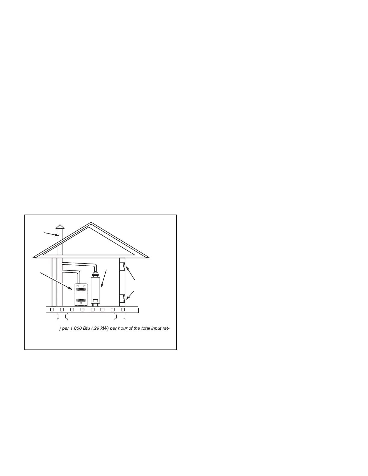
EQUIPMENT IN CONFINED
SPACE ALL AIR FROM INSIDE
CHIMNEY
OR GAS
VENT
FURNACE
WATER
HEATER
OPENINGS
(To Adjacent
Room)
NOTE - Each opening shall have a free area of at least one square
inch (645 mm
2
ing of all equipment in the enclosure, but not less than 100 square
inches (64516 mm
2
).
AIR FLOW
FIGURE 2
Air from Inside
If the conned space that houses the furnace adjoins a
space categorized as unconned, air can be brought in by
providing two permanent openings between the two spac-
es. Each opening must have a minimum free area of 1
square inch (645 mm2) per 1,000 Btu (.29 kW) per hour of
total input rating of all gas-red equipment in the conned
space. Each opening must be at least 100 square inches
(64516 mm2). One opening shall be within 12 inches (305
mm) of the top of the enclosure and one opening within 12
inches (305 mm) of the bottom. See FIGURE 2.
Air from Outside
If air from outside is brought in for combustion and ventila-
tion, the conned space must have two permanent open-
ings. One opening shall be within 12 inches (305 mm) of
the top of the enclosure and one opening within 12 inches
(305 mm) of the bottom. These openings must commu-
nicate directly or by ducts with the outdoors or spaces
(crawl or attic) that freely communicate with the outdoors
or indirectly through vertical ducts. Each opening shall
have a minimum free area of 1 square inch (645 mm2)
per 4,000 Btu (1.17 kW) per hour of total input rating of
all equipment in the enclosure. See FIGURE 3 and FIG-
URE 4. When communicating with the outdoors through
horizontal ducts, each opening shall have a minimum free
area of 1 square inch (645 mm2) per 2,000 Btu (.56 kW)
per total input rating of all equipment in the enclosure. See
FIGURE 5.
When ducts are used, they shall be of the same cross-sec-
tional area as the free area of the openings to which they
connect. The minimum dimension of rectangular air ducts
shall be no less than 3 inches (75 mm). In calculating free
area, the blocking eect of louvers, grilles, or screens
must be considered. If the design and free area of protec-
tive covering is not known for calculating the size opening
required, it may be assumed that wood louvers will have
20 to 25 percent free area and metal louvers and grilles
will have 60 to 75 percent free area. Louvers and grilles
must be xed in the open position or interlocked with the
equipment so that they are opened automatically during
equipment operation.
 Loading...