Page 24
CAUTION
If this unit is being installed in an application with
combustion air coming in from a space serviced by an
exhaust fan, power exhaust fan, or other device which
may create a negative pressure in the space, take care
ZKHQVL]LQJWKHLQOHWDLURSHQLQJ7KHLQOHWDLURSHQLQJ
PXVW EH VL]HG WR DFFRPPRGDWH WKH PD[LPXP YROXPH
of exhausted air as well as the maximum volume of
combustion air required for all gas appliances serviced
by this space.
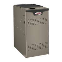
EQUIPMENT IN CONFINED SPACE
(Inlet Air from Ventilated Attic and Outlet Air to Outside)
NOTE-The inlet and outlet air openings shall each have a free area
of at least one square inch per 4,000 Btu (645mm
2
per 1.17kW) per
hour of the total input rating of all equipment in the enclosure.
Ventilation Louvers
Inlet Air
(Minimum
12 in.(305mm) Above
attic floor)
Roof Terminated
Exhaust Pipe
Furnace
*Intake Debris
Screen
(Provided)
Figure 29
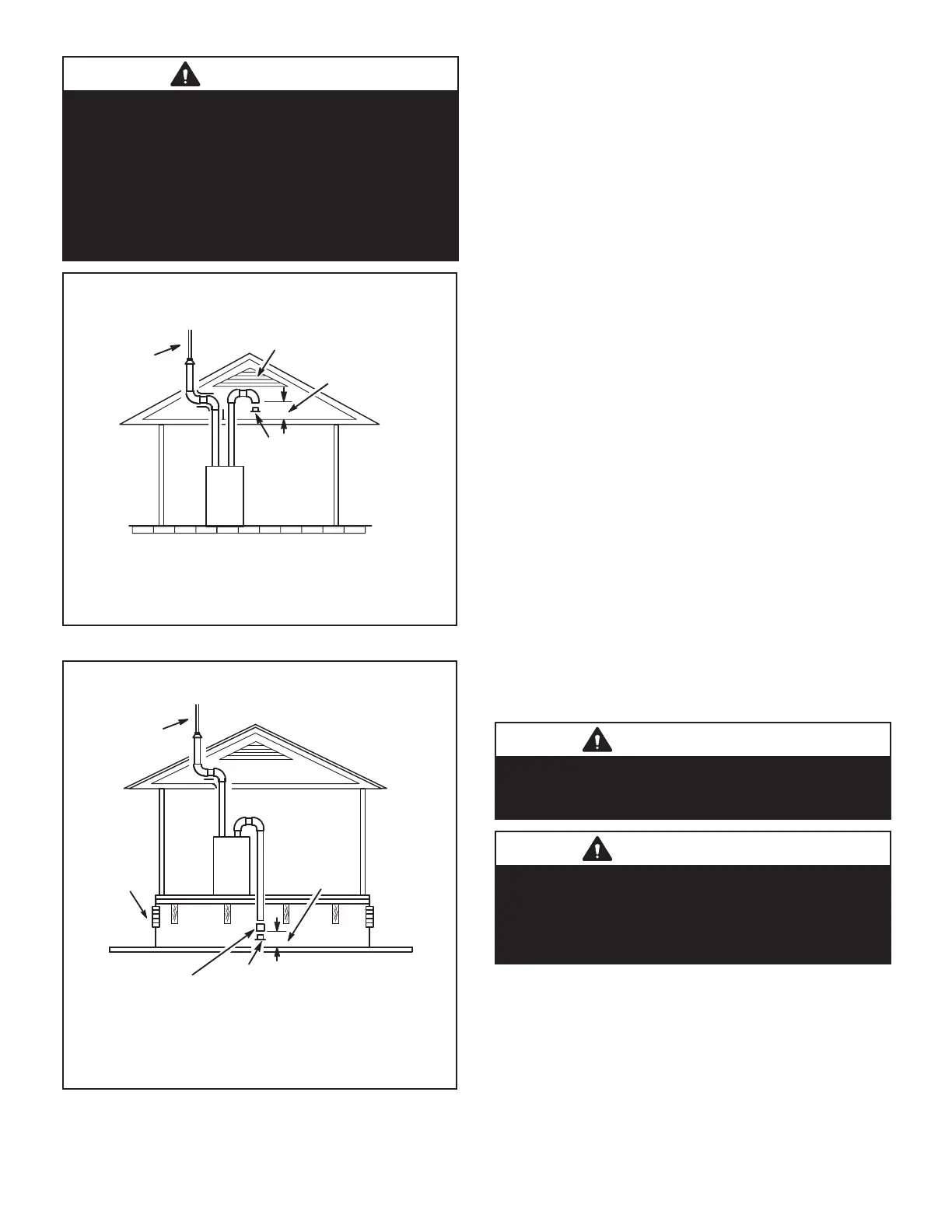
NOTE-The inlet and outlet air openings shall each have a free area
of at least one square inch per 4,000 Btu (645mm
2
per 1.17kW) per
hour of the total input rating of all equipment in the enclosure.
EQUIPMENT IN CONFINED SPACE
(Inlet Air from Ventilated Crawlspace and Outlet Air to Outside)
Roof Terminated
Exhaust Pipe
Furnace
Ventilation
Louvers
(Crawl space)
*Intake Debris Screen Provided)
Inlet Air
(Minimum
12 in.(305mm)
Above crawl
space floor)
Coupling or
3 in. to 2 in.
Transition
(Field Provided)
Figure 30
General Guidelines for Vent Terminations
In Non-Direct Vent applications, combustion air is taken
IURPLQGRRUVDQGWKHÀXHJDVHVDUHGLVFKDUJHGWRWKHRXW-
GRRUV7KH(/8+(LVWKHQFODVVL¿HG DV D QRQGLUHFW
vent, Category IV gas furnace.
In Direct Vent applications, combustion air is taken from
RXWGRRUV DQG WKH ÀXH JDVHV DUH GLVFKDUJHG WR WKH RXW-
GRRUV7KH(/8+(LVWKHQFODVVL¿HGDVDGLUHFWYHQW
Category IV gas furnace.
In both Non-Direct Vent and Direct Vent applications, the
vent termination is limited by local building codes. In the
absence of local codes, refer to the current National Fuel
Gas Code ANSI Z223-1/NFPA 54 in U.S.A., and current
CSA-B149 Natural Gas and Propane Installation Codes in
Canada for details.
Position termination according to location given in Figure
32 or Figure 33. In addition, position termination so it is
free from any obstructions and 12” above the average
snow accumulation.
At vent termination, care must be taken to maintain protec-
tive coatings over building materials (prolonged exposure
to exhaust condensate can destroy protective coatings).
It is recommended that the exhaust outlet not be located
within 6 feet (1.8m) of an outdoor AC unit because the
condensate can damage the painted coating.
NOTE - 6HH7$%/(IRUPD[LPXPDOORZHGH[KDXVWSLSH
OHQJWK ZLWKRXW LQVXODWLRQ LQ XQFRQGLWLRQHG VSDFH GXULQJ
ZLQWHUGHVLJQWHPSHUDWXUHVEHORZ)&,IUHTXLUHG
H[KDXVW SLSH VKRXOG EH LQVXODWHG ZLWK ´ PP $U-
PDÀH[RUHTXLYDOHQW,QH[WUHPHFROGFOLPDWHDUHDV´
PP$UPDÀH[RU HTXLYDOHQWPD\EHQHFHVVDU\,QVX-
ODWLRQPXVWEHSURWHFWHGIURPGHWHULRUDWLRQ$UPDÀH[ZLWK
89 SURWHFWLRQ LV SHUPLVVDEOH %DVHPHQWV RU RWKHU HQ-
FORVHGDUHDVWKDWDUHQRWH[SRVHGWRWKHRXWGRRUDPELHQW
WHPSHUDWXUHDQGDUHDERYHGHJUHHV)&DUHWREH
FRQVLGHUHGFRQGLWLRQHGVSDFHV
IMPORTANT
Do not use screens or perforated metal in exhaust
WHUPLQDWLRQV 'RLQJ VR ZLOO FDXVH IUHH]HXSV DQG PD\
block the terminations.
IMPORTANT
For Canadian Installations Only:
In accordance to CSA International B149 installation
codes, the minimum allowed distance between the
combustion air intake inlet and the exhaust outlet of other
appliances shall not be less than 12 inches (305mm).
 Loading...