Page 36
Gas Piping
Gas supply piping should not allow more than 0.5”W.C.
drop in pressure between gas meter and unit. Supply gas
pipe must not be smaller than unit gas connection.
CAUTION
,IDÀH[LEOHJDVFRQQHFWRULVUHTXLUHGRUDOORZHGE\WKH
authority that has jurisdiction, black iron pipe shall be
installed at the gas valve and extend outside the furnace
FDELQHW 7KH ÀH[LEOH FRQQHFWRU FDQ WKHQ EH DGGHG
between the black iron pipe and the gas supply line.
WARNING
Do not over torque (800 in-lbs) or under torque (350 in-
lbs) when attaching the gas piping to the gas valve.
1 - Gas piping may be routed into the unit through either
the left- or right-hand side. Supply piping enters into
the gas valve from the side of the valve as shown
in Figure 56. Connect the gas supply piping into the
gas valve. The maximum torque is 800 in lbs and
minimum torque is 350 in lbs when when attaching
the gas piping to the gas valve.
2 - When connecting gas supply, factors such as length
RI UXQ QXPEHU RI ¿WWLQJV DQG IXUQDFH UDWLQJ PXVW
be considered to avoid excessive pressure drop.
7$%/( OLVWV UHFRPPHQGHG SLSH VL]HV IRU W\SLFDO
applications.
NOTE - 8VH WZR ZUHQFKHV ZKHQ FRQQHFWLQJ JDV
SLSLQJWRDYRLGWUDQVIHUULQJWRUTXHWRWKHPDQLIROG
3 - Gas piping must not run in or through air ducts,
clothes chutes, chimneys or gas vents, dumb waiters
or elevator shafts. Center gas line through piping
hole. Gas line should not touch side of unit. See
Figure 56 and Figure 57.
4 - Piping should be sloped 1/4 inch per 15 feet (6mm
per 5.6m) upward toward the gas meter from the
furnace. The piping must be supported at proper
intervals, every 8 to 10 feet (2.44 to 3.05m), using
suitable hangers or straps. Install a drip leg in
vertical pipe runs to serve as a trap for sediment or
condensate.
5 - A 1/8” N.P.T. plugged tap or pressure post is located
on the gas valve to facilitate test gauge connection.
6HH¿JXUH
6 - In some localities, codes may require installation of a
PDQXDOPDLQVKXWRႇYDOYHDQGXQLRQIXUQLVKHGE\
installer) external to the unit. Union must be of the
ground joint type.
IMPORTANT
Compounds used on threaded joints of gas piping must
EHUHVLVWDQWWRWKHDFWLRQVRIOLTXL¿HGSHWUROHXPJDVHV
Leak Check
After gas piping is completed, carefully check all piping
FRQQHFWLRQV IDFWRU\ DQG ¿HOGLQVWDOOHG IRU JDV OHDNV
Use a leak detecting solution or other preferred means.
1HYHUXVHDQRSHQÀDPHWRWHVWIRUJDVOHDNV&KHFNDOO
connections using a commercially available soap solution
PDGHVSHFL¿FDOO\IRUOHDNGHWHFWLRQ
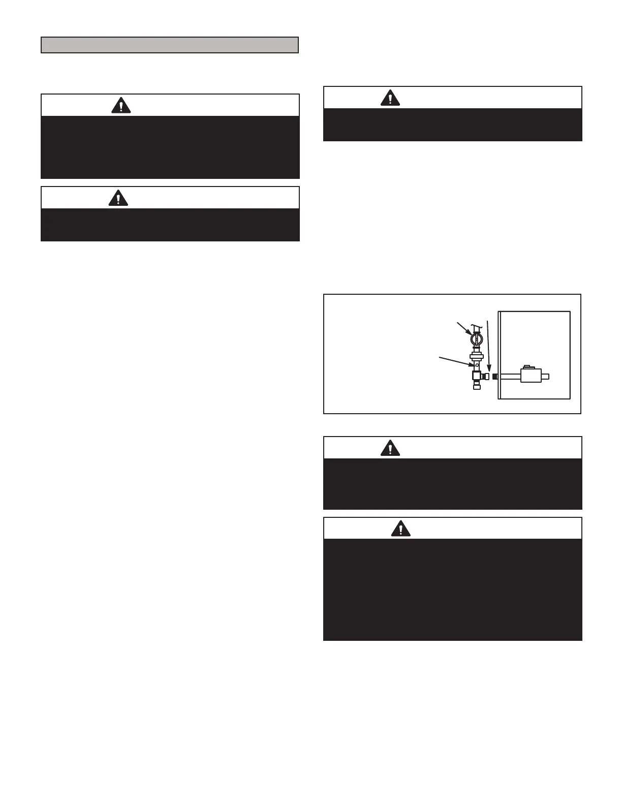
7KHIXUQDFHPXVWEHLVRODWHGIURPWKHJDVVXSSO\V\VWHP
E\FORVLQJLWVLQGLYLGXDOPDQXDOVKXWR௺YDOYHGXULQJDQ\
SUHVVXUH WHVWLQJ RI WKH JDV VXSSO\ V\VWHP DW SUHVVXUHV
JUHDWHUWKDQRUHTXDOWRSVLJN3DLQFKHVZF
MANUAL MAIN SHUT-OFF
VALVE WILL NOT HOLD
NORMAL TEST PRESSURE
CAP
FURNACE
ISOLATE
GAS VALVE
1/8” N.P.T. PLUGGED TAP
Figure 55
IMPORTANT
When testing pressure of gas lines, gas valve must be
disconnected and isolated. See Figure 55. Gas valves
can be damaged if subjected to pressures greater than
1/2 psig (3.48 kPa).
WARNING
FIRE OR EXPLOSION HAZARD
Failure to follow the safety warnings exactly could result
in serious injury, death, or property damage. Never use
DQRSHQÀDPHWRWHVWIRUJDVOHDNV&KHFNDOOFRQQHFWLRQV
using a commercially available soap solution made
VSHFL¿FDOO\IRUOHDNGHWHFWLRQ6RPHVRDSVXVHGIRUOHDN
detection are corrosive to certain metals. Carefully rinse
piping thoroughly after leak test has been completed.

 Loading...