Page 31
Details of Exhaust Piping Terminations for Non-Direct
Vent Applications
([KDXVWSLSHVPD\EHURXWHGHLWKHU KRUL]RQWDOO\WKURXJK
an outside wall or vertically through the roof. In attic or
closet installations, vertical termination through the roof
is preferred. Figure 43 and Figure 44 show typical termi-
nations.
1 - Exhaust piping must terminate straight out or up as
VKRZQ7KHWHUPLQDWLRQSLSHPXVWEHVL]HGDVOLVWHG
LQ7$%/(7KHVSHFL¿HGSLSHVL]HHQVXUHVSURSHU
velocity required to move the exhaust gases away
from the building.
2Q ¿HOG VXSSOLHG WHUPLQDWLRQV IRU VLGH ZDOO H[LW
exhaust piping may extend a maximum of 12 inches
(305mm) for 2” PVC and 20 inches (508mm) for 3”
(76mm) PVC beyond the outside wall.
3 - If exhaust piping must be run up a side wall to position
above snow accumulation or other obstructions,
piping must be supported every 24 inches (610mm).
When exhaust piping must be run up an outside wall,
DQ\ UHGXFWLRQ LQ H[KDXVW SLSH VL]H PXVW EH GRQH
DIWHUWKH¿QDOHOERZ
4 - Distance between exhaust pipe terminations on
multiple furnaces must meet local codes.
NON-DIRECT VENT ROOF TERMINATION KIT
(15F75 or 44J41)
UNCONDITIONED
ATTIC SPACE
3” (76mm) OR
2” (51mm) PVC
PROVIDE SUPPORT
FOR EXHAUST LINES
12” (305mm)
ABOVE AVE.
SNOW
ACCUMULATION
Figure 43
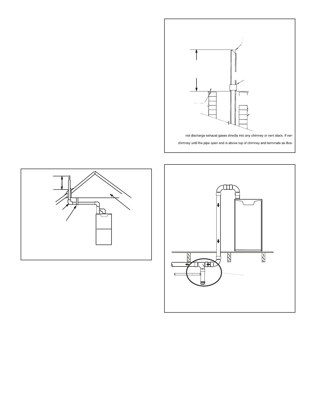
Crawl Space and Extended Horizontal Venting
Lennox provides kit 51W18 (USA) kit 15Z70 (Canada) to
LQVWDOO´RU´39&H[KDXVWSLSLQJWKURXJKWKHÀRRUMRLVWV
and into the the crawl space. See Figure 45. This kit can
also be used as a supplemental drain for installations with
FRQGHQVDWHUXQEDFNLQWKHYHQWSLSHLHORQJKRUL]RQWDO
runs, unconditioned spaces, etc.).
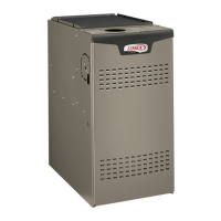
NOTE - Do
tical discharge through an existing unused chimney or stack is required, insert piping
inside
trated. In any exterior portion of chimney, the exhaust vent must be insulated.
STRAIGHT-CUT OR
ANGLE-CUT IN DIRECTION
OF ROOF SLOPE
SHOULDER OF FITTINGS
PROVIDE SUPPORT
OF PIPE ON TOP PLATE
EXTERIOR
PORTION OF
CHIMNEY
INSULATE
TO FORM
SEAL
SHEET
METAL TOP
PLATE
NON-DIRECT VENT APPLICATION
USING EXISTING CHIMNEY
Minimum 12” (305MM)
above chimney top
plate or average snow
accumulation
Figure 44
Venting In A Crawl Space
Basement Floor
KIT 51W18
(USA)
KIT 15Z70
(CANADA)
Figure 45
Condensate Piping
This unit is designed for either right- or left-side exit of
FRQGHQVDWH SLSLQJ LQ XSÀRZ DSSOLFDWLRQV ,Q KRUL]RQWDO
applications, the condensate trap must extend below the
unit. An 8” service clearance is required for the conden-
sate trap.
 Loading...