Page 38
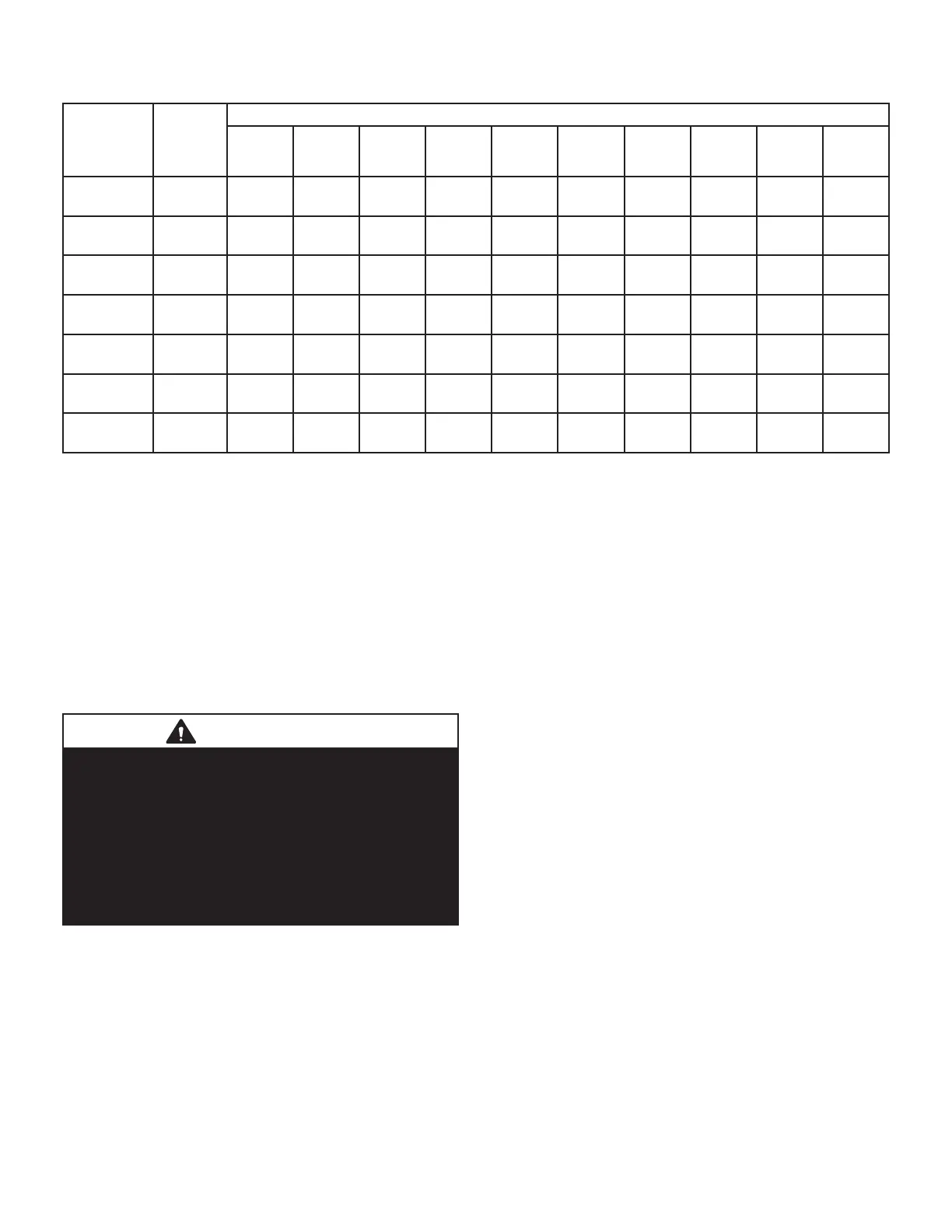
TABLE 9
Gas Pipe Capacity - ft3/hr (m3/hr)
Nominal
Iron Pipe
6L]H,QFKHV
(mm)
Internal
Diameter
inches
(mm)
Length of Pipe - feet (m)
10
(3.048)
20
(6.096)
30
(9,144)
40
(12,192)
50
(15.240)
60
(18.288)
70
(21.336)
80
(24.384)
90
(27.432)
100
(30,480)
1/2
(12.7)
.622
(17.799)
172
(4.87)
118
(3.34)
95
(2.69)
81
(2.29)
72
(2.03)
65
(1.84)
60
(1.69)
56
(1.58)
52
(1.47)
50
(1.42)
3/4
(19.05)
.824
(20.930)
360
(10.19)
247
(7.000)
199
(5.63)
170
(4.81)
151
(4.23)
137
(3.87)
126
(3.56)
117
(3.31)
110
(3.11)
104
(2.94)
1
(25.4)
1.049
(26.645)
678
(19.19)
466
(13.19)
374
(10.59)
320
(9.06)
284
(8.04)
257
(7.27)
237
(6.71)
220
(6.23)
207
(5.86)
195
(5.52)
1-1/4
(31.75)
1.380
(35.052)
1350
(38.22)
957
(27.09)
768
(22.25)
657
(18.60)
583
(16.50)
528
(14.95)
486
(13.76)
452
(12.79)
424
(12.00)
400
(11.33)
1-1/2
(38.1)
1.610
(40.894)
2090
(59.18)
1430
(40.49)
1150
(32.56)
985
(27.89)
873
(24.72)
791
(22.39)
728
(20.61)
677
(19.17)
635
(17.98)
600
(17.00)
2
(50.8)
2.067
(52.502)
4020
(113.83)
2760
(78.15)
2220
(62.86)
1900
(53.80)
1680
(47.57)
1520
(43.04)
1400
(39.64)
1300
(36.81)
1220
(34.55)
1160
(32.844)
2-1/2
(63.5)
2.469
(67.713)
6400
(181.22)
4400
(124.59)
3530
(99.95)
3020
(85.51)
2680
(75.88)
2480
(70.22)
2230
(63.14)
2080
(58.89)
1950
(55.22)
1840
(52.10)
NOTE -&DSDFLW\JLYHQLQFXELFIHHWPRIJDVSHUKRXUDQGEDVHGRQVSHFL¿FJUDYLW\JDV
Removal of the Furnace from Common Vent
In the event that an existing furnace is removed from a
venting system commonly run with separate gas applianc-
es, the venting system is likely to be too large to properly
vent the remaining attached appliances.
Conduct the following test while each appliance is oper-
ating and the other appliances (which are not operating)
remain connected to the common venting system. If the
venting system has been installed improperly, you must
correct the system as indicated in the general venting re-
quirements section.
WARNING
CARBON MONOXIDE POISONING HAZARD
Failure to follow the steps outlined below for each
appliance connected to the venting system being placed
into operation could result in carbon monoxide poisoning
or death.
The following steps shall be followed for each appliance
connected to the venting system being placed into
operation, while all other appliances connected to the
venting system are not in operation:
1 - Seal any unused openings in the common venting
system.
,QVSHFW WKH YHQWLQJ V\VWHP IRU SURSHU VL]H DQG
KRUL]RQWDOSLWFK'HWHUPLQHWKDWWKHUHLVQREORFNDJH
UHVWULFWLRQOHDNDJHFRUURVLRQRURWKHU GH¿FLHQFLHV
which could cause an unsafe condition.
3 - Close all building doors and windows and all
doors between the space in which the appliances
remaining connected to the common venting system
are located and other spaces of the building. Turn on
clothes dryers and any appliances not connected to
the common venting system. Turn on any exhaust
fans, such as range hoods and bathroom exhausts,
so they will operate at maximum speed. Do not
RSHUDWH D VXPPHU H[KDXVW IDQ &ORVH ¿UHSODFH
dampers.
4 - Follow the lighting instructions. Turn on the appliance
that is being inspected. Adjust the thermostat so that
the appliance operates continuously.
5 - After the main burner has operated for 5 minutes,
WHVW IRU OHDNV RI ÀXH JDVHV DW WKH GUDIW KRRG UHOLHI
RSHQLQJ8VHWKHÀDPHRIDPDWFKRUFDQGOH
6 - After determining that each appliance connected to
the common venting system is venting properly, (step
UHWXUQ DOO GRRUV ZLGRZV H[KDXVW IDQV ¿UHSODFH
dampers, and any other gas-burning appliances to
their previous mode of operation.
7 - If a venting problem is found during any of the
preceding tests, the common venting system must
EHPRGL¿HGWRFRUUHFWWKHSUREOHP
5HVL]H WKH FRPPRQ YHQWLQJ V\VWHP WR WKH PLQLPXP
YHQW SLSH VL]H GHWHUPLQHG E\ XVLQJ WKH DSSURSULDWH
tables in Appendix G. (These are in the current stan-
dards of the National Fuel Gas Code ANSI Z223.1.

 Loading...