Page 43
Priming Condensate Trap
The condensate trap should be primed with water prior
to start-up to ensure proper condensate drainage. Either
SRXU À R] PO RI ZDWHU LQWR WKH WUDS RU IROORZ
these steps to prime the trap:
1 - Follow the lighting instructions to place the unit into
operation.
2 - Set the thermostat to initiate a heating demand.
$OORZWKHEXUQHUVWR¿UHIRUDSSUR[LPDWHO\PLQXWHV
4 - Adjust the thermostat to deactivate the heating
demand.
5 - Wait for the combustion air inducer to stop. Set the
thermostat to initiate a heating demand and again
DOORZWKHEXUQHUVWR¿UHIRUDSSUR[LPDWHO\PLQXWHV
6 - Adjust the thermostat to deactivate the heating
demand and wait for the combustion air inducer to
stop. At this point, the trap should be primed with
VXႈFLHQW ZDWHU WR HQVXUH SURSHU FRQGHQVDWH GUDLQ
operation.
WARNING
,I\RXGRQRWIROORZWKHVHLQVWUXFWLRQVH[DFWO\D¿UHRU
explosion may result causing property damage, personal
injury or death.
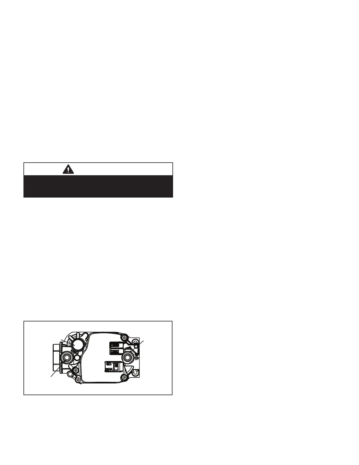
Gas Valve Operation (Figure 61)
1 - |STOP! Read the safety information at the beginning
of this section.
2 - Set the thermostat to the lowest setting.
7XUQRႇDOOHOHFWULFDOSRZHUWRWKHXQLW
4 - This furnace is equipped with an ignition device
which automatically lights the burners. Do not try to
light the burners by hand.
5 - Remove the access panel.
6 - Move gas valve switch to OFF. See Figure 61.
:DLW ¿YH PLQXWHV WR FOHDU RXW DQ\ JDV ,I \RX WKHQ
smell gas, STOP! Immediately call your gas supplier
from a neighbor’s phone. Follow the gas supplier’s
instructions. If you do not smell gas go to next step.
8 - Move gas valve switch to ON. See Figure 61.
GAS VALVE SHOWN IN ON POSITION
MANIFOLD
PRESSURE
OUTLET
PORT
INLET
PRESSURE
PORT
MANIFOLD
PRESSURE
ADJUSTMENT
SCREW
Figure 61
9 - Replace the access panel.
10- Turn on all electrical power to to the unit.
11- Set the thermostat to desired setting.
NOTE - :KHQXQLWLVLQLWLDOO\VWDUWHGVWHSVWKURXJK
PD\QHHGWREHUHSHDWHGWRSXUJHDLUIURPJDV
OLQH
12- If the appliance will not operate, follow the
LQVWUXFWLRQV³7XUQLQJ2ႇ*DVWR8QLW´DQGFDOO\RXU
service technician or gas supplier.
7XUQLQJ2ႇ*DVWR8QLW
1 - Set the thermostat to the lowest setting.
7XUQRႇDOOHOHFWULFDOSRZHUWRWKHXQLWLIVHUYLFHLVWR
be performed.
3 - Remove the access panel.
4 - Move gas valve switch to OFF.
5 - Replace the access panel.
Failure To Operate
If the unit fails to operate, check the following:
1 - Is the thermostat calling for heat?
2 - Are access panels securely in place?
3 - Is the main disconnect switch closed?
4 - Is there a blown fuse or tripped breaker?
,VWKH¿OWHUGLUW\RUSOXJJHG"'LUW\RUSOXJJHG¿OWHUV
ZLOOFDXVHWKHOLPLWFRQWUROWRVKXWWKHXQLWRႇ
6 - Is gas turned on at the meter?
,VWKHPDQXDOPDLQVKXWRႇYDOYHRSHQ"
,VWKHLQWHUQDOPDQXDOVKXWRႇYDOYHRSHQ"
9 - Is the unit ignition system in lockout? If the unit locks
out again, inspect the unit for blockages.
Heating Sequence Of Operation
1 - When thermostat calls for heat, combustion air
inducer starts.
2 - Combustion air pressure switch proves blower
operation. Switch is factory set and requires no
adjustment.
3 - After a 15-second prepurge, the hot surface ignitor
HQHUJL]HV
4 - After a 20-second ignitor warm-up period, the gas
valve solenoid opens. A 4-second trial for ignition
period begins.”
*DVLV LJQLWHG ÀDPH VHQVRUSURYHVWKHÀDPHDQG
the combustion process continues.
,I ÀDPH LV QRW GHWHFWHG DIWHU ¿UVW LJQLWLRQ WULDO WKH
ignition control will repeat steps 3 and 4 four
more times before locking out the gas valve
³:$7&+*8$5'´ÀDPHIDLOXUHPRGH7KHLJQLWLRQ
control will then automatically repeat steps 1 through
6 after 60 minutes. To interrupt the 60-minute
“WATCHGUARD” period, move thermostat from
“Heat” to “OFF” then back to “Heat”. Heating
sequence then restarts at step 1.

 Loading...