Page 128 - IOM / ROOF-TOP FLEXY™ Series
MAINTENANCE PLAN
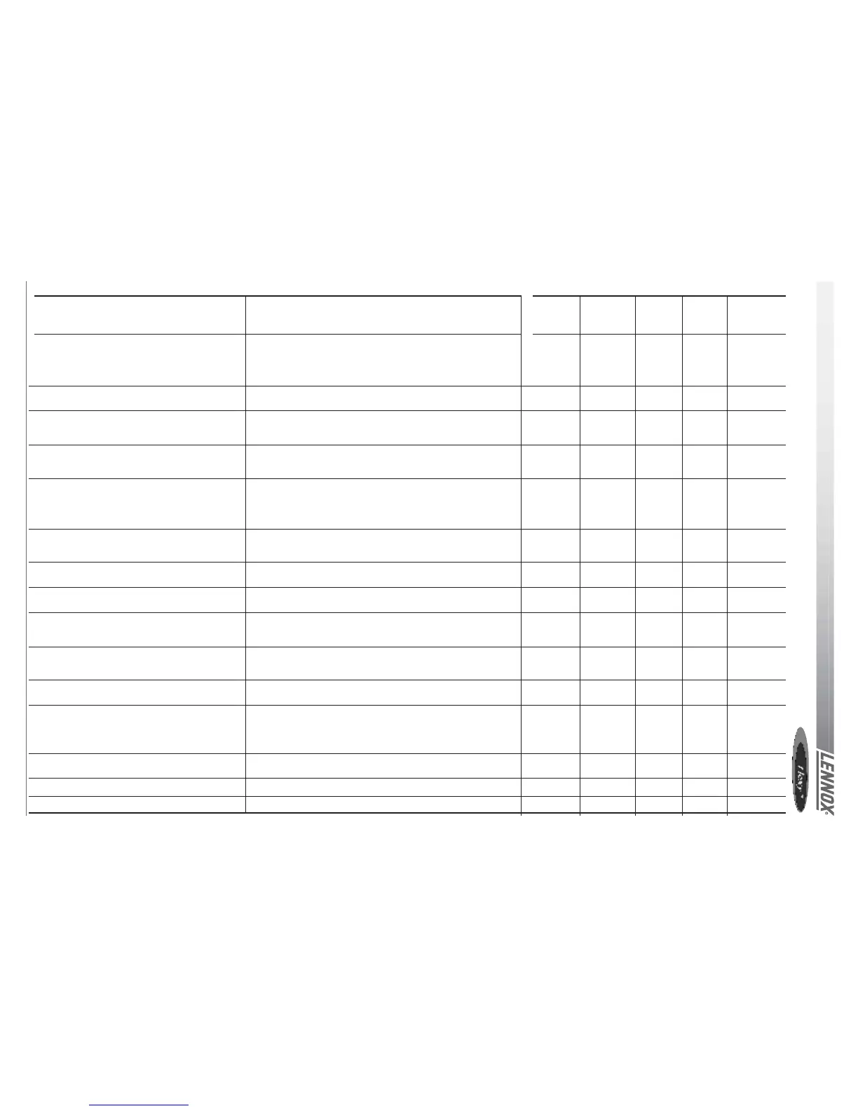
TASK
Check HP / LP safety switches
Check outdoor fans and fan guards
Check position of all sensors
Check and clean if necessary all fresh air
grilles
Check indoor and outdoor coils, clean if
necessary
Check electric heater element for excessive
corrosion
Check anti-vibration mountings, for wear and
tear.
Check refrigeration circuit for traces of acid
in the oil
Check Glycol concentration in the HWC
circuit
Check defrost cycle with 4-way valve inver-
sion.
Gas burner module check for corrosion
Sweeping and cleaning the gas burner
Gas supply pressures / connections
checks
Gas regulation valve settings
Check gas burner safety switches
OPERATING MODE
Install manifold gauges on the circuit to be checked. Shut down
the axial fans and wait for the HP switch to shut down the
compressor: 29bar (+1 / -0) auto-reset 22bar (+ - 0.7)
Reconnect fans. Switch off the centrifugal supply fan and wait
for the LP switch to cut out: 0.5bar (+ - 0.5) reset 1.5bar (+-0.5).
Check the fan blades conditions and all fan guards and protec-
tions
Check the good positioning and operation of all sensors of all
sensors. Check the values given in the control system. Replace
sensor if necessary
Check the fresh air grilles (if fitted). If dirty or damaged, remove
them from unit and clean with high pressure water cleaner. Refit
on unit once clean and dry.
Visually check the coils for dirt. If not too dirty, cleaning with a
light brush may be enough (WARNING: Fins and copper tubes
are very fragile! Any damage WILL reduce the performances of
the unit). If very dirty, deep industrial cleaning is required using
de-greasing agents.(External contractors must be called).
Isolate the unit; Pull the electric heater out of the heater module
box and check the resistances fo traces of corrosion; Replace
resistance as required;
Visually check anti-vibration mountings on compressors and
centrifugal fan. Replace if damaged.
Take a sample of oil from the refrigeration circuit.
Check the glycol concentration in the pressurised water circuit.
( a concentration of 30% gives a protection down to aprox. -
15°C) check the circuit pressure
Switch the unit to heat pump mode. Change the set point to
obtain the standard defrost mode and reduce the cycle time to
the min value. Check the operation of the defrost cycle.
Pull out the burner to access the tubes (refer to Gas burner
section in the IOM)
Clean the in-shot burners and the blower wheel lightly with a
brush. Sweep the flue and flue box. Wipe-off the dust from the
housing of the motor. Clean combustion air inlet louvers Pull-out
baffles from the tubes, sweep the tubes
CHECK FLUE BOX GASKET
refer to Gas burner section in the IOM for details
refer to Gas burner section in the IOM for details
refer to Gas burner section in the IOM for details
6 YEARLY ESTIMATED
MONTHLY QUARTERLY MONTHLY B4 TIME
WINTER (mn)
∆ 15
0 5
0 5
0 5
0 / ∆ 1h if cleaning
0 1h if
replacement
0 1h if
replacement
∆
∆ 30
∆ 30
∆ 30
∆ 30
∆ 15
∆ 30
∆ 30
 Loading...