IOM / ROOF-TOP FLEXY™ Series - Page 45
GAS BURNER
1. PRELIMINARY CHECKS AND VERIFI-
CATIONS BEFORE START-UP
NOTE :
ANY WORK ON THE GAS SYSTEM MUST BE
CARRIED OUT BY QUALIFIED PERSONNEL.
THIS UNIT MUST BE INSTALLED IN
ACCORDANCE WITH LOCAL SAFETY CODES
AND REGULATIONS AND CAN ONLY BE USED IN
WELL VENTILLATED AREA.
PLEASE READ CAREFULLY THE
MANUFACTURER'S INSTRUCTIONS BEFORE
STARTING A UNIT.
BEFORE COMMISSIONING A UNIT WITH GAZ
BURNER, IT IS MANDATORY TO ENSURE THAT
THE GAZ DISTRIBUTION SYSTEM (type of gas,
available pressure…) IS COMPATIBLE WITH THE
ADJUSTMENT AND SETTINGS OF THE UNIT.
1.1 Check access and clearances around the
unit :
- Make sure one can move freely around the unit
- A one-meter clearance must be left in front of the burnt
gas exhaust chimney(s)
- Combustion air inlet and burnt gas exhaust(s) must not
be obstructed in any way.
1.2 Supply network pipe sizing
- The gas supply to a
rooftop gas unit must
be according to Sound
Engineering Practice.
- The pipe-work
connected to each
rooftop must not be
smaller than the
diameter of the
connection on the
rooftop unit.
1.3 Shut-off valve in front of each rooftop
- Make sure that a shut off isolation valve has been
installed before EACH rooftop.
- Check that the internal shut off valves in the rooftop unit
is open.
1.4 Pipe-work purging and gas static pressure
checks
- Purge the pipe-work
near the connection on
the HONEYWELL valve
for a few seconds
Standard GN 20 mbar :
Check the pressure at the
inlet of the HONEYWELL
valve.
GN 300 mbar option with pressure regulator :
Check the pressure at the regulator inlet.
Propane 37 mbar option :
Check the pressure at the inlet of the HONEYWELL valve.
Propane 148 mbar option with pressure regulation
(yellow spring) :
Check the pressure at the regulator inlet. A 10% tolerance
around the nominal pressure is acceptable.
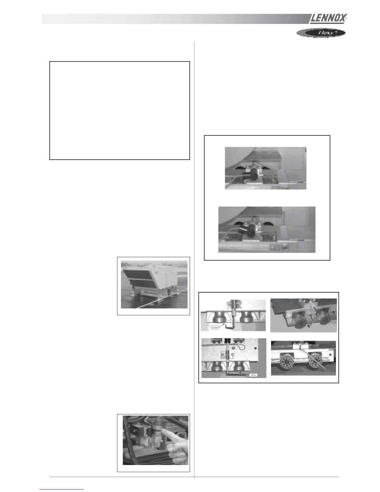
1.5 Probes and electrodes position check
Visually check that the ionisation probe is centred in the middle
of the flame.
Check that the end of the ignition electrode is aligned with the
side of the inshot burner.
Figure 40
Figure 41
INCORRECT
CORRECT
Figure 42
Figure 43