Page 16 - IOM / ROOF-TOP FLEXY™ Series
THIS WORK MUST ONLY BE CARRIED OUT
BY TRAINED REFRIGERATION ENGINEERS
Before connecting the power :
- Ensure that the power supply between the building and
the unit meets local authority standards and that the
cable specification satisfies the start-up and operating
conditions.
- Ensure that the electrical connections in the control
panel and on the motors are secure.
- Ensure that all drive motors are secure.
- Ensure that the adjustable pulley blocks are secure and
that the belt is tensioned with the transmission correctly
aligned.
- Using the electrical wiring diagram, check the conformity
of the electrical safety devices (circuit breaker settings,
presence and rating of fuses).
At this point attach the manometers to the refrigerant circuit
Powering up the system with the unit isolating
switch
- Close the blower circuit breaker and the 24V control.
- Power up the unit by closing the isolator switch. At this
point the blower should start unless the CLIMATIC™
does not energise the contactor. In this particular case
the blower can be forced by bridging the COM and NO
wires on the connector J1 on the CLIMATIC controller.
Once the fan is running check the rotation direction.
Refer to the rotation arrow on the fan.
- The fan and other components direction of rotation is
checked during an end of line test. They should
therefore all turn in the same direction.
- If they run in the opposite direction, disconnect the
power supply to the machine at the building's mains
switch, reverse two phases of the incoming supply to the
machine and try again.
Using CLIMATIC™
- Check the voltages recorded against the rated values, in
particular on the system supply fans.
- If the readings on the fans are outside the limits, this
indicates excessive air flow which will affect the
thermodynamic performance. Refer to the "Air flow
balancing" section.
COMMISSIONING
1. Check the configuration
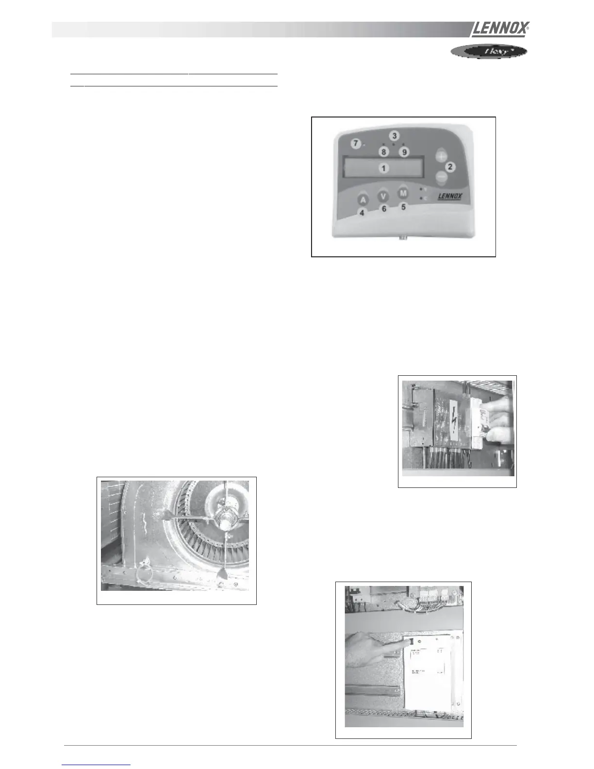
- You will need a KP02 maintenance controller or
CLIMALOOK with KP 14 interface.
1 Liquid crystal display
2 Raise/lower keys
3 "FILTER" Led (flashing red)
4 "ADDRESS" key
5 "MODE" key
6 "VALUE" key
7 "UNIT RUNNING" led
8 "MODE" led
9 "GENERAL ALARM" led.
- The jumpers are
factory set and the
configuration switches
are adjusted
depending on the
option selection and
the type of unit.
- Close the 24V control circuit breakers
- The CLIMATIC™ is starting. Wait for 30 seconds.
1.1 Check and adjust the factory configuration
- Reset the DAD smoke detector (if fitted)
Figure 14
Figure 13
Figure 16
Figure 15