IOM / ROOF-TOP FLEXY™ Series - Page 25
AIRFLOW BALANCING
EXAMPLE
The unit used for this example is a FHK 060N with standard supply and return airflow configuration. It is also fitted with an
economiser and an electric heater type H.
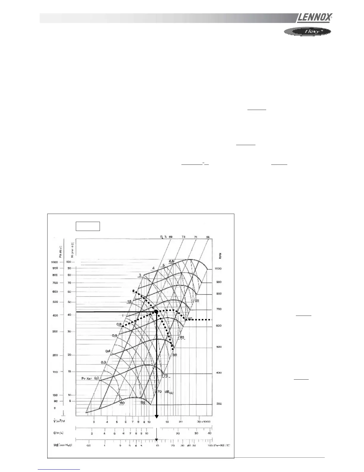
It is fitted with a AT 18-18 fan which curve is shown on page xxx and a 2.2 kW motor.
- Motor rpm : 1430 rpm
- cos ϕ = 0.81
- Voltage = 400 V
- Current = 4,68A
P
mech fan
= V x I x
√√
√√
√ 3 x cos
ϕ ϕ
ϕ ϕ
ϕ x
ηη
ηη
η
mech motor
x
ηη
ηη
η
Transmission
= 400 x 4.68 x
√√
√√
√ 3 x 0.81 x 0.76 x 0.9 = 1,79 kW
The unit is also fitted with a transmission kit 1
- Fixed Fan pulley : 250 mm
- Motor adjustable pulley type "8450" opened 1 turn from fully closed or measured distance between pulley end plates is
21,8 mm: from table xxx it can be determined that the motor pulley has a diameter of 111,8 mm
rpm
FAN
= rpm
MOTOR
x D
M
/ D
F
= 1430 x 118,2 / 250 = 640 rpm
Using the fan curve below the operating point can be located.
It can be determined that the fan is providing approximately
12 000 m
3
/h with a total pressure P
TOT
= 420 Pa
640
420
12
10
1.79
Hd (mmH2O)
AT 18-18
The pressure losses in the unit are the
sum of all pressure drops across the
different parts of a unit :
- Coil and filter (measured) = 105 Pa
- Options = 6 Pa for economiser and
8 Pa for electric heater H
∆P = 105 + 6 + 8 =
119 Pa
The dynamic pressure at 1200m
3
/h is
given at the bottom of the fan curve
Pd = 100 Pa
The external static pressure available is
therefore
ESP = P
TOT
- Pd - ∆PI
NT
= 420 - 100 - 119 = 201 Pa
Figure 24