Page 15
6 − Set the thermostat for a cooling demand, turn on power
to indoor blower unit and close the outdoor unit discon-
nect to start the unit.
7 − Recheck voltage while the unit is running. Power must
be within range shown on the nameplate.
Charging
This system is charged with R410A refrigerant which oper-
ates at much higher pressures than R22. The recom-
mended check expansion valve is approved for use with
R410A. Do not replace it with a valve that is designed to be
used with R22. This unit is NOT approved for use with coils
that include metering orifices or capillary tubes.
Processing Procedure
The unit is factory−charged with the amount of R410A re-
frigerant indicated on the unit rating plate. This charge is
based on a matching indoor coil and outdoor coil with a 15
foot (4.6 m) line set. For varying lengths of line set, refer to
table 2 for refrigerant charge adjustment. A blank space is
provided on the unit rating plate to list the actual field
charge.
Table 4
Liquid Line Set
Diameter
Oz. per 5 ft. (grams per 1.5 m) adjust
from 15 ft. (4.6 m) line set*
3/8 in.
(10 mm)
3 ounces per 5 feet
(85 g per 1.5 m)
*If line length is greater than 15 ft. (4.6 m), add this amount.
If line length is less than 15 ft. (4.6 m), subtract this amount.
IMPORTANT
Mineral oils are not compatible with R410A. If oil
must be added, it must be a polyol ester oil.
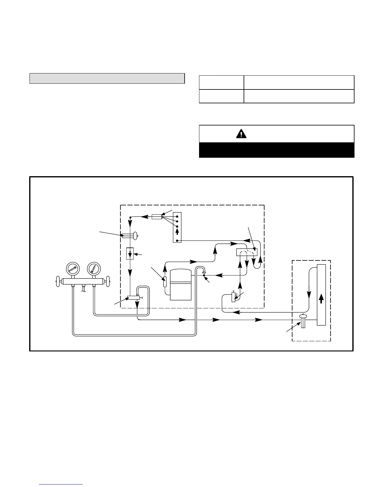
HPXA12 COOLING CYCLE
(Showing Gauge Manifold Connections)
NOTE−Use gauge ports on vapor line valve and liquid valve for evacuating refrigerant lines
and indoor coil. Use vapor gauge port to measure vapor pressure during charging.
OUTDOOR
COIL
EXPANSION/
CHECK VALVE
BIFLOW
FILTER / DRIER
TO
R410A
DRUM
LOW
PRESSURE
HIGH
PRESSURE
COMPRESSOR
REVERSING VALVE
VAPOR
LINE
VALVE
MUFFLER
NOTE − ARROWS INDICATE
DIRECTION OF REFRIGERANT FLOW
SERVICE
PORT
VAPOR
EXPANSION/CHECK
VALVE
INDOOR UNIT
OUTDOOR UNIT
LIQUID
LINE
SERVICE
PORT
GAUGE MANIFOLD
DISTRIBUTOR
INDOOR
COIL
Figure 15
 Loading...

