Page 13
To Close Service Valve:
1 − Remove stem cap with an adjustable wrench.
2 − Use a service wrench with a hex head extension to turn
the stem clockwise to seat the valve. Tighten firmly.
NOTE − Use a 3/16" hex head extension for liquid line
sizes or a 5/16" extension for vapor line sizes.
3 − Replace stem cap. Tighten finger tight, then tighten an
additional 1/6 turn.
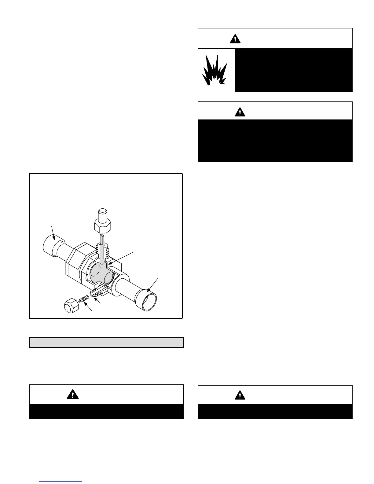
Ball−Type Vapor Valve
Vapor line service valves function the same way as the oth-
er valves, the difference is in the construction. These
valves are not rebuildable. If a valve has failed, you must
replace it. A ball valve valve is illustrated in figure 14.
The ball valve is equipped with a service port with a factory−
installed Schrader valve. A service port cap protects the
Schrader valve from contamination and assures a leak−
free seal.
Vapor Line (Ball Type) Service Valve
(Valve Open)
Figure 14
Schrader valve
service port
service port
cap
stem cap
stem
Use adjustable wrench
To open: Rotate stem counter-clockwise 90.
To close: Rotate stem clockwise 90.
ball
(shown open)
to outdoor coil
to indoor coil
Leak Testing
After the line set has been connected to the indoor and
outdoor units, check the line set connections and indoor
unit for leaks.
WARNING
Refrigerant can be harmful if it is inhaled. Refriger-
ant must be used and recovered responsibly.
WARNING
Danger of explosion: Can cause
equipment damage, injury or death.
Never use oxygen to pressurize a re-
frigeration or air conditioning system.
Oxygen will explode on contact with
oil and could cause personal injury.
WARNING
Danger of explosion: Can cause equipment damage,
injury or death. When using a high pressure gas
such as dry nitrogen to pressurize a refrigeration or
air conditioning system, use a regulator that can
control the pressure down to 1 or 2 psig (6.9 to 13.8
kPa).
Using an Electronic Leak Detector
1 − Connect a cylinder of R410A to the center port of the
manifold gauge set.
2 − With both manifold valves closed, open the valve on
the R410A cylinder (vapor only).
3 − Open the high pressure side of the manifold to allow
the R410A into the line set and indoor unit. Weigh in a
trace amount of R410A . [A trace amount is a maximum
of 2 ounces (57 g) or 3 pounds (31 kPa) pressure.]
Close the valve on the R410A cylinder and the valve
on the high pressure side of the manifold gauge set.
Disconnect the R410A cylinder.
4 − Connect a cylinder of nitrogen with a pressure regulat-
ing valve to the center port of the manifold gauge set.
5 − Connect the manifold gauge set high pressure hose to
the vapor valve service port. (Normally, the high pres-
sure hose is connected to the liquid line port; however,
connecting it to the vapor port better protects the man-
ifold gauge set from high pressure damage.)
6 − Adjust the nitrogen pressure to 150 psig (1034 kPa).
Open the valve on the high side of the manifold gauge
set which will pressurize line set and indoor unit.
7 − After a few minutes, open a refrigerant port to ensure
the refrigerant you added is adequate to be detected.
(Amounts of refrigerant will vary with line lengths.)
Check all joints for leaks. Purge nitrogen and R410A
mixture. Correct any leaks and recheck.
IMPORTANT
Leak detector must be capable of sensing HFC re-
frigerant.
 Loading...

