Page 11
4 − Remove the pressure tap valve cores from the
HPXA12 unit’s service valves. Connect an R22 cylin-
der with clean refrigerant to the vapor service valve.
Connect the R22 gauge set to the liquid line valve and
connect a recovery machine with an empty recovery
tank to the gauge set.
5 − Set the recovery machine for liquid recovery and start
the recovery machine. Open the gauge set valves to
allow the recovery machine to pull a vacuum on the ex-
isting system line set and indoor coil.
6 − Invert the cylinder of clean R22 and open its valve to
allow liquid refrigerant to flow into the system through
the vapor line valve. Allow the refrigerant to pass from
the cylinder and through the line set and the indoor coil
before it enters the recovery machine.
7 − After all of the liquid refrigerant has been recovered,
switch the recovery machine to vapor recovery so that
all of the R22 vapor is recovered. All the recovery ma-
chine to pull a vacuum on the system.
NOTE − A single system flush should remove all of the
mineral oil from the existing refrigerant lines and in-
door coil. A second flushing may be done (using clean
refrigerant) if insufficient amounts of mineral oil were
removed during the first flush. Each time the system
is flushed, you must allow the recovery machine
to pull a vacuum on the system at the end of the
procedure.
8 − Close the valve on the inverted R22 drum and the
gauge set valves. Pump the remaining refrigerant out
of the recovery machine and turn the machine off.
9 − Use nitrogen to break the vacuum on the refrigerant
lines and indoor coil before removing the recovery ma-
chine, gauges and R22 refrigerant drum. Reinstall
pressure tap valve cores into HPXA12 service valves.
10 −Install the provided check/expansion valve (approved
for use with R410A refrigerant) in the liquid line at the
indoor coil.
Refrigerant Metering Device
HPXA12 units are applicable to check expansion valve
systems only. See indoor coil installation instructions and
the Lennox engineering handbook for approved R410A
TXV match−ups and application information.
NOTE − R410A systems will not operate properly with an
R−22 valve.
Check Expansion Valve Systems
Check expansion valves equipped with either Chatleff or
flare−type fittings are available from Lennox. Refer to the
Engineering Handbook for applicable expansion valves
for use with specific match-ups. See table 2 for applicable
check and expansion valve kits.
If you install a check expansion valve with an indoor coil
that includes a fixed orifice, remove the orifice before
the check expansion valve is installed.
IMPORTANT
Failure to remove RFC when installing an expansion
valve to the indoor coil will result in improper opera-
tion and damage to the system.
Table 2
Indoor Check Expansion Valve Kits
Model Kit Catalog Number
HPXA12−018
HPXA12−024
HPXA12−030
HPXA12−036
49L24
HPXA12−042
HPXA12−048
HPXA12−060
49L25
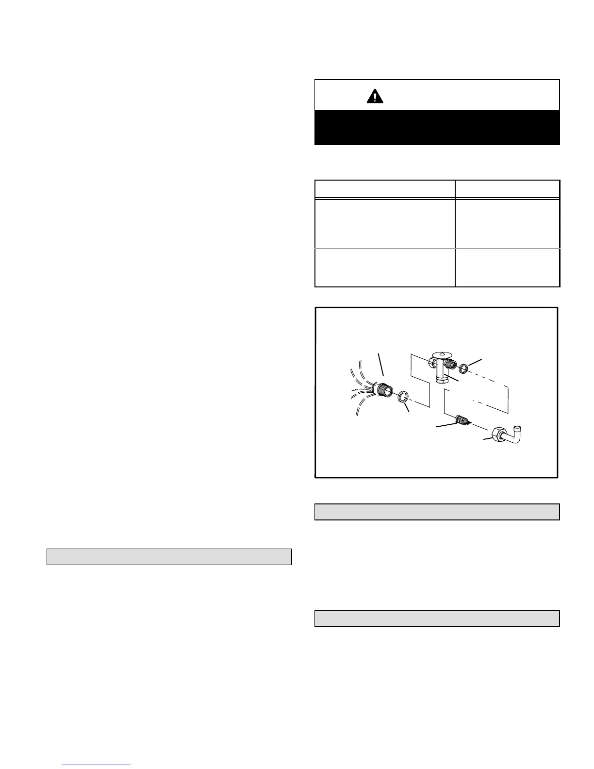
See figure 12 for installation of the check expansion valve.
Metering Device Installation
expansion
valve
o−ring
o−ring
strainer
liquid line
stub
distributor
Figure 12
Manifold Gauge Set
Manifold gauge sets used with systems charged with
R410A refrigerant must be capable of handling the higher
system operating pressures. The gauges should be rated
for use with pressures of 0 − 800 on the high side and a low
side of 30" vacuum to 250 psi with dampened speed to 500
psi. Gauge hoses must be rated for use at up to 800 psi of
pressure with a 4000 psi burst rating.
Service Valves
The liquid line and vapor line service valves (figures 13 and
14) and gauge ports are used for leak testing, evacuating,
charging and checking charge. See table 3 for torque re-
quirements.
Each valve is equipped with a service port which has a fac-
tory−installed Schrader valve. A service port cap protects
the Schrader valve from contamination and serves as the
primary leak seal.
 Loading...

