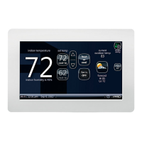
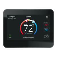
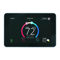
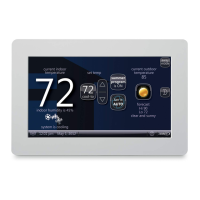
iComfort Wi‐Fi
®
7-Day Programmable Communicating Thermostat
45
Figure 21. Wiring the Digital Ventilation Controller (iComfort Series Thermostat)
Thermostat Wire Termination in Communicating System
Indoor Unit
Controller
Outdoor Unit
iComfort Wi‐Fi
®
thermostat
Single wire to
terminal C
Single wire to
terminal C
Unused wires
Unused wires
RSBus
Minimum wire size is 18
gauge
Maximum total length of all connections on the RSBus is limited to
1500 ft. (450 m). Max. length between components is 300 ft. (90 m).
Note: iComfort Wi‐Fi
®
thermostat does not require shielded cable wiring.
BEST PRACTICES! Keep all communication wiring as far away from house electric
al wiring and large electrical appliances as possible (15' [5m] recommended).
Communicating systems using the iComfort Wi‐Fi
®
thermostat require four
thermostat wires between the thermostat and the furnace/air handler control
and four wires between the outdoor unit and the furnace/air handler control.
When a thermostat cable with more than four wires is used, the extra wires
must be properly connected to avoid electrical noise. The wires must not be
left disconnected.
Use wire nuts to bundle the unused wires at each end of the cable. A single
wire should then be connected to the indoor unit end of the wire bundle and
attached to the “C” terminals as shown in the diagram above.
This is not an issue in non-communicating systems.
 Loading...
