5
5. Trim 1/4 inch (6 mm) insulation from end of each
thermostat wire lead.
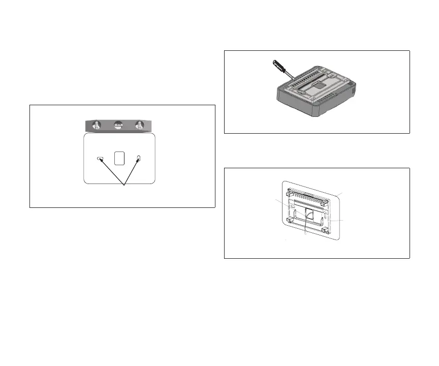
6. Use the provided wall plate as a template on
where to drill the mounting holes.
NOTE: Installation of wall plate is optional. Use
a eld-provided level to allow for proper
alignment.
(Use a level) Align Wall Plate
Use unit wall plate as template to mark desired
mounting hole locations on wall.
7. Drill 3/16” (5 mm) holes in wall for provided wall
anchors. Insert provided wall anchors into drilled
holes.
8. Remove back plate from main zone sensor
assembly using a at-head screw driver.
9. Route wiring from wall through center openings
on wall plate (use is optional) and back plate.
Wall Plate (optional)
Zone Sensor Back Plate
Run thermostat wire
through openings

 Loading...