7
SENSE 24VAC
PRESSURE SW
C SENSE
DATS
D+
PWR
D-
C
ZONE 5
D+
PWR
D-
C
ZONE 2/6
D+
PWR
D-
C
ZONE 3/7
D+
PWR
D-
C
ZONE 4/8
1 – 4
5 - 8
Zone Sensor
C
D-
D+
PWR
NOT USED
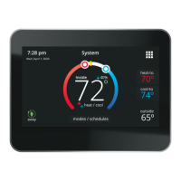
Figure 2. Connecting Zone Sensor to Damper
Control Module
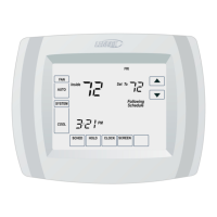
Unused wires
Single wire
to terminal “C”.
Damper Control Module
17A30 Zone Sensor
PWR D+ D- C
SENSE 24VAC
PRESSURE SW
C SENSE
DATS
D+
PWR
D-
C
ZONE 5
D+
PWR
D-
C
ZONE 2/6
D+
PWR
D-
C
ZONE 3/7
D+
PWR
D-
C
ZONE 4/8
1 – 4
5 - 8
Figure 3. Communicating and Low Voltage
Connections
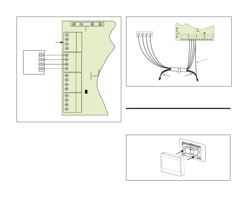
install Zone sensor to BaCkPlate
The zone sensor assembly simply snaps onto the
back plate. Once secure to the back plate apply
power to the system. The zone sensor should boot
up and go into the commissioning process.
Figure 4. Installing Zone Sensor

 Loading...