Page 28
On multiple unit installations, each unit should be checked
separately while operating at maximum rate, beginning with
the one closest to the supply gas main and progressing to
the one furthest from the main. Multiple units should also
be tested with and without the other units operating.
Supply pressure must fall within the range listed in the
previous paragraph.
4-Check and Adjust Manifold Pressure
After line pressure has been checked and adjusted,
check manifold pressure. Move test gauge to the outlet
pressure tap located on unit gas valve GV1. See figure 17
for location of pressure tap on the gas valve.
The manifold pressure is factory set and should not re
quire adjustment. See table 12. If manifold pressure is incor
rect and no other source of improper manifold pressure can be
found, the valve must be replaced. See figure 17 or 18 for lo
cation of gas valve (manifold pressure) adjustment screw.
All gas valves are factory-regulated. The gas valve should
completely and immediately cycle off in the event of gas or
power failure. The manual shut‐off knob can be used to imme
diately shut off gas supply.
CAUTION
For safety, connect a shut‐off valve between the
manometer and the gas tap to permit shut off of
gas pressure to the manometer.
Manifold Adjustment Procedure
1- Connect test gauge to the outlet pressure tap on the
gas valve. Start the unit (call for second-stage heat)
and allow five minutes for the unit to reach steady
state.
2- While waiting for the unit to stabilize, notice the
flame. The flame should be stable without flashback
and should not lift from the burner heads. Natural
gas should burn basically blue with some clear
streaks. L.P. gas should burn mostly blue with some
clear yellow streaks.
3- After allowing the unit to stabilize for five minutes,
record the manifold pressure and compare to the val
ues given in table 3.
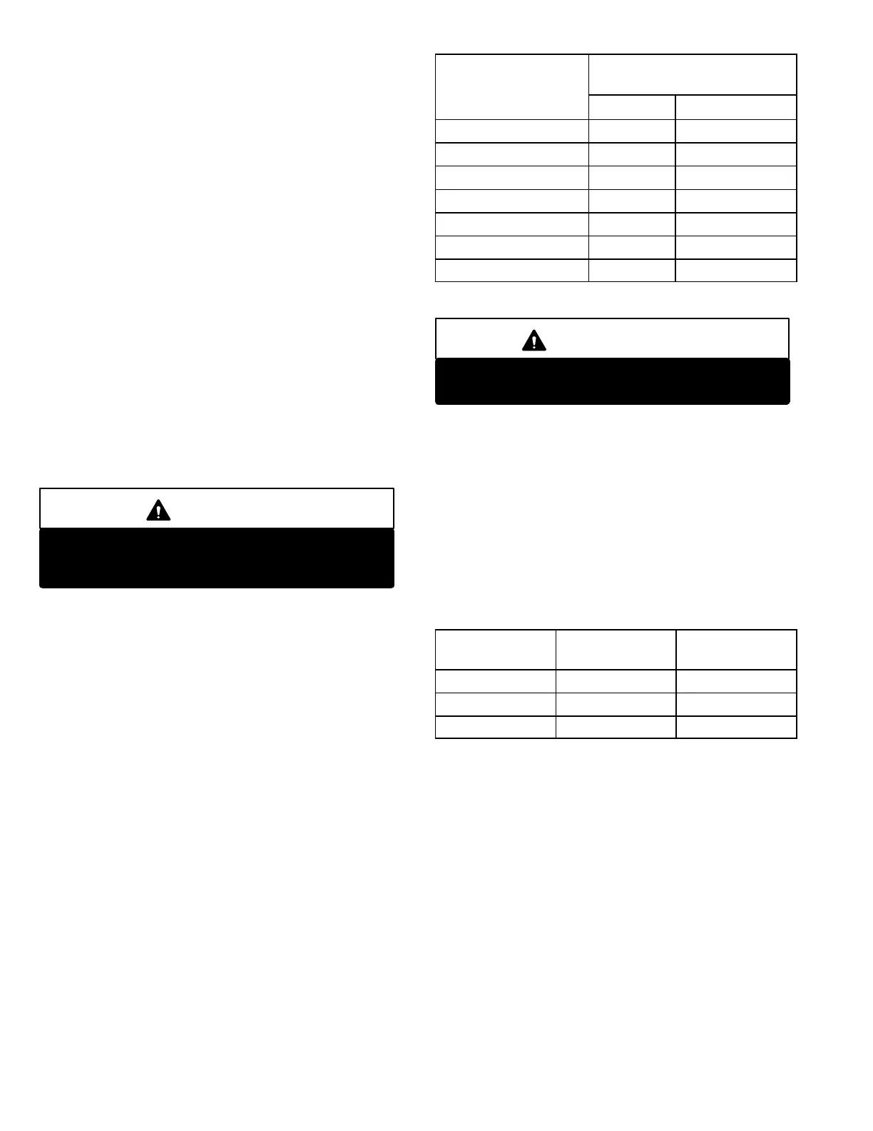
5-High Altitude
Units may be installed at altitudes up to 2000 feet (610 m)
above sea level without any modification. At altitudes
above 2000 feet (610 m), units must be derated to match
the gas manifold pressures shown in table 12.
NOTE ‐ This is the only permissible derate for these units.
TABLE 12
Altitude - ft. (m)
Gas Manifold Pressure
in. w.g. (kPa)
Natural LP (Propane)
0 - 2000 ( 610) 3.7 (0.92) 10.5 (2.61)
2001 - 3000 ( 610 - 915) 3.6 (0.90) 10.2 (2.54)
3001 - 4000 ( 915 - 1220) 3.5 (0.87) 9.9 (2.46)
4001 - 5000 (1220 - 1525) 3.4 (0.85) 9.6 (2.39)
5001 - 6000 (1525 - 1830) 3.3 (0.82) 9.4 (2.34)
6001 - 7000 (1830 - 2135) 3.2 (0.80) 9.1 (2.26)
7001 - 8000 (2135 - 2440) 3.1 (0.77) 8.8 (2.19)
*Contact Technical Support for altitudes higher than 8000 ft. (2400m).
IMPORTANT
Disconnect heating demand as soon as an
accurate reading has been obtained.
6-Proper Gas Flow
Furnace should operate at least 5 minutes before checking
gas flow. Determine time in seconds for two revolutions of
gas through the meter. (Two revolutions assures a more ac
curate time.) Divide by two and compare to time in table 13.
Seconds in table 13 are based on a 1 cu.ft. dial and gas val
ue of 1000 btu's for natural and 2500 btu's for LP. Adjust
manifold pressure on gas valve to match time needed.
NOTE - To obtain accurate reading, shut off all other gas
appliances connected to meter.
TABLE 13
Unit in Btu's
Seconds for
Natural
Seconds for
Propane
130,000 28 69
180,000 20 50
240,000 15 37
7-Heat Exchanger
To Access or Remove Heat Exchanger From Unit:
1- Turn off gas and electric power.
2- Remove access panel(s) and unit center mullion.
3- Remove gas valve, manifold assembly and burn
ers.
4- Remove combustion air inducer and flue box cover.
Pay careful attention to the order in which gaskets and
orifice are removed.
5- Support heat exchanger (to prevent it from falling
when final screws are removed.)
6- Remove screws supporting heat exchanger.
7- To install heat exchanger, reverse procedure. Be sure
to secure all wires and check plumbing and burner
plate for airtight seal. Screws must be torqued to 35
in.‐lbs. to ensure proper operation.
 Loading...
