Page 11
508288-01 9/2022
B-New Installations
Once the app is downloaded, refer to the Setup Guide
provided with this unit to pair the app to the unit control
system. Follow the setup wizard prompts to configure the
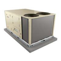
unit. See figure 7 for the app menu overview. If a mobile
device is unavailable or not pairing, refer to the Unit
Controller Setup Guide for start-up instructions.
MOBILE SERVICE APP MENU OVERVIEW
MENU
RTU MENU
SETUP
INSTALL
NETWORK
INTEGRATION
TEST AND BALANCETEST AND BALANCE
ALARM HISTORY
DATA TRENDING
FACTORY
RUNTIMES
SYSTEM DATA /
SENSORS / OUTPUTS
SERVICE
COMPONENT TEST
REPORT
ADVANCED
CONTROL
FIRMWARE UPDATE
SETTINGS
RTU OPTION
INSTALL
FIGURE 7
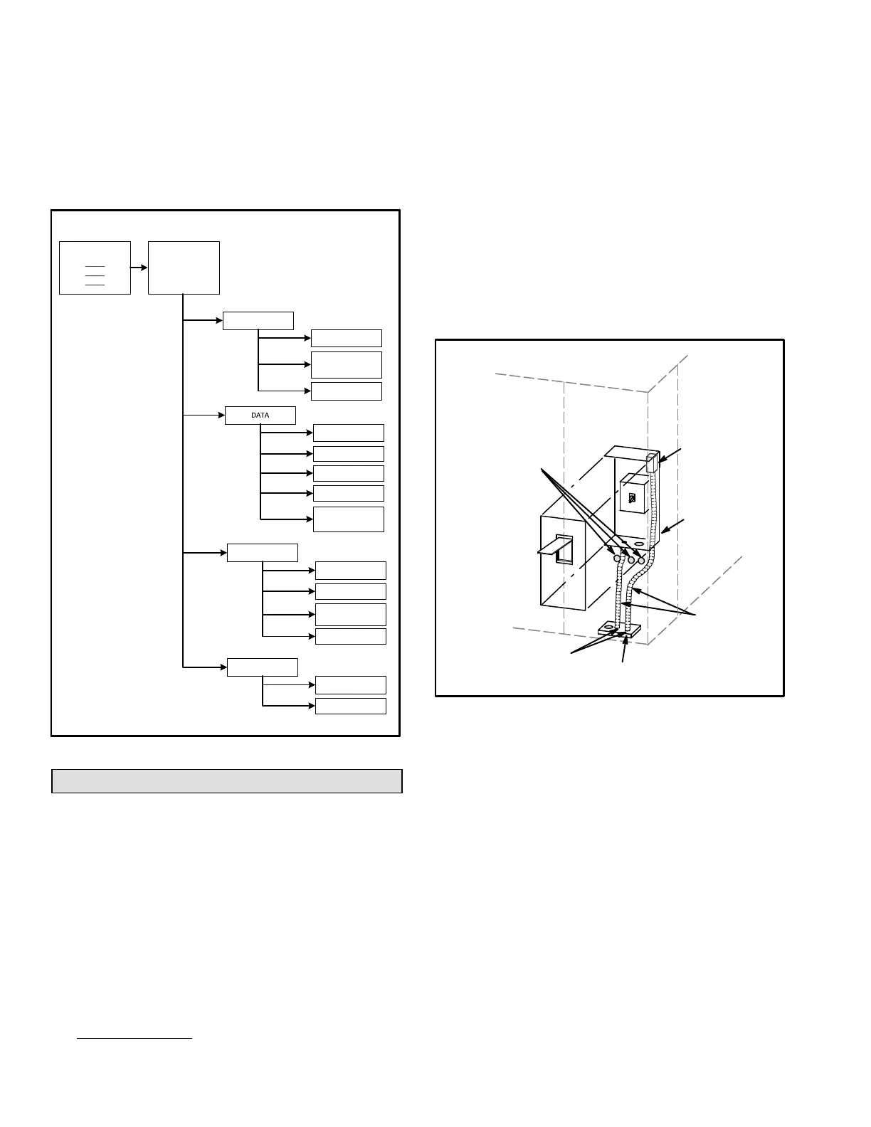
Electrical Connections - Power Supply
A-Wiring
Route field wiring in conduit between bottom power entry
and disconnect. See figure 8. This does not supersede
local codes or authorities having jurisdiction.
Do not apply power or close disconnect switch until
installation is complete. Refer to start-up directions.
Refer closely to unit wiring diagram.
Refer to unit nameplate for minimum circuit ampacity
and maximum fuse size.
1- Units are factory-wired for 240/460/575 volt supply.
For 208V supply,
remove the insulated terminal
cover from the 208V terminal on the control
transformer. Move the wire from the transformer
240V terminal to the 208V terminal. Place the
insulated terminal cover on the unused 240V
terminal.
2- Route power through the bottom power entry area
and connect to line side of unit disconnect, circuit
breaker or terminal block. See unit wiring diagram.
3- Units With Optional 120v GFCI Outlet -
Route and connect separate 120v wiring to GFCI
outlets which do not have factory-installed wiring.
Route field wiring in conduit between bottom power
entry and GFCI. See figure 8.
SEAL
WATERTIGHT
RUN FIELD
WIRING IN
FIELD PRO
VIDED CONDUIT
SIDE ENTRY
KNOCKOUTS
BOTTOM
POWER ENTRY
OPTIONAL
120V GFI
MAKE-
UP BOX
FIGURE 8
FIELD WIRE ROUTING
B-Unbalanced Three-Phase Voltage
Units equipped with an inverter (VFD) are designed to
operate on balanced, three-phase power. Operating units
on unbalanced three-phase power will reduce the
reliability of all electrical components in the unit.
Unbalanced power is a result of the power delivery
system supplied by the local utility company.
Factory-installed inverters are sized to drive blower
motors with an equivalent current rating using balanced
three-phase power. When unbalanced three-phase
power is supplied; the installer must replace the existing
factory-installed inverter with an inverter that has a higher
current rating to allow for the imbalance. Use table 2 to
determine the appropriate replacement inverter.
 Loading...