Page 73
508288-01 9/2022
Hot Gas Reheat Start-Up
General
Hot gas reheat units provide a dehumidifying mode of
operation. These units contain a reheat coil adjacent to
and downstream of the evaporator coil. Reheat coil
solenoid valves, L14 and L30, route hot discharge gas
from the compressor to the reheat coil. Return air pulled
across the evaporator coil is cooled and dehumidified;
the reheat coil adds heat to supply air.
See figure 33 through 38 for refrigerant routing.
L14 and L30 Reheat Coil Solenoid Valves
When Unit Controller (P298-5 or J299-8) indicates room
conditions require dehumidification, See figure 11
through 13. L14 and L30 reheat valves are energized
(Unit Controller J394-1 or J394-3) and refrigerant is
routed to the reheat coil.
Reheat Setpoint
Reheat is factory-set to energize when indoor relative
humidity rises above 60% (default). The reheat setpoint
can be adjusted by changing mobile service app Settings
- Control menu. A setting of 100% will operate reheat from
an energy management system digital output. The reheat
setpoint can also be adjusted using an optional Network
Control Panel (NCP).
Reheat will terminate when the indoor relative humidity
falls 3% (57% default) or the digital output de-energizes.
The reheat deadband can be adjusted at Settings -
Control menu.
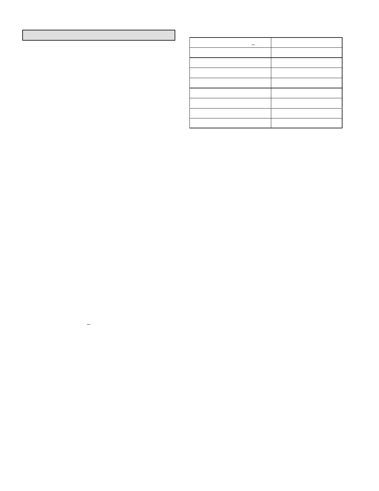
A91 Humidity Sensor
Relative humidity should correspond to the sensor (A91)
output voltage listed in table 20. For example: if indoor air
relative humidity is 80% +
3%, the humidity sensor output
should read 8.00VDC.
Check the sensor output annually for accuracy. Keep the
air intake openings on the sensor clean and free of
obstructions and debris.
TABLE 20
Relative Humidity (%RH + 3%) Sensor Output (VDC)
20 2.00
30 3.00
40 4.00
50 5.00
60 6.00
70 7.00
80 8.00
90 9.00
Check-Out
Test hot gas reheat operation using the following
procedure.
1- Make sure reheat is wired as shown in wiring section.
2- Make sure unit is in local thermostat mode.
3- Use mobile service app menu path to select:
SERVICE > TEST > DEHUMIDIFIER
The blower, compressor 1 and compressor 2 (reheat)
should be operating. Reheat mode will appear on the
mobile service app display.
4- Deselect:
SERVICE > TEST > DEHUMIDIFIER
Compressor 1 and 2 (reheat should de-energize, blower
should still be energized.
Additional Cooling Stages
Units are shipped from the factory to provide two stages of
cooling.
Compressors are not de-energized when unit operation
changes from cooling to reheat or from reheat to cooling.
Instead, L14 and L30 reheat valves are energized
(reheat) or de-energized (cooling).
NOTE - Another thermostat staging option is available
which allows both compressors to be energized during
free cooling. See Unit Controller manual for details.
 Loading...