Page 13
508288-01 9/2022
D-Hot Gas Reheat Units Only
1- Install humidity sensor in accordance with instructions
provided with sensor. A DDC input may be used to
initiate dehumidification instead of a sensor.
2- Make wiring connections as shown in figure 9 for
Thermostat Mode and figure 10 for Zone Sensor
Mode. In addition, connect either a humidity sensor
or a dehumidification input. See figure 11 or 12 for
humidity sensor wiring and figure 13 for
dehumidification input wiring.
Humidity Sensor Cable Applications:
Wire runs of 50 feet (mm) or less:
Use two separate shielded cables containing 20AWG
minimum, twisted pair conductors with overall shield.
Belden type 8762 or 88760 (plenum) or equivalent.
Connect both cable shield drain wires to TB1-7 as shown
in figure 11.
Wire runs of 150 feet (mm) or less:
Use two separate shielded cables containing 18AWG
minimum, twisted pair conductors with overall shield.
Belden type 8760 or 88760 (plenum) or equivalent.
Connect both cable shield drain wires to TB1-7 as shown
in figure 11.
Wire runs over 150 feet (mm):
Use a local, isolated 24VAC transformer such as Lennox
cat #18M13 (20VA minimum) to supply power to RH
sensor as shown in figure 12. Use two shielded cables
containing 20AWG minimum, twisted pair conductors
with overall shield. Belden type 8762 or 88760 (plenum)
or equivalent.
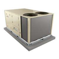
FIGURE 11
FIELD WIRING REHEAT UNITS (Using A Humidity
Sensor With Less Than 150 Ft. Wire Runs)
9
8
J298
P298
1
2
3
4
5
6
7
10
A91
VIN
VO
GND
R
C
AI-1
HUM
TMP
AI2
C
R
UNUSED
WIRE
NOT
CONNECTED
NOT
CONNECTED
DRAIN
A55 UNIT
CONTROLLER
FIGURE 12
FIELD WIRING REHEAT UNITS (Using A Humid
ity Sensor With More than 150 Ft. Wire Runs)
ISOLATED 24V
TRANSFORMER
9
8
J298P298
1
2
3
4
5
6
7
10
A91
VIN
VO
GND
R
C
AI-1
HUM
TMP
AI2
C
R
NOT
CONNECTED
NOT
CONNECTED
DRAIN
A55 UNIT
CONTROLLER
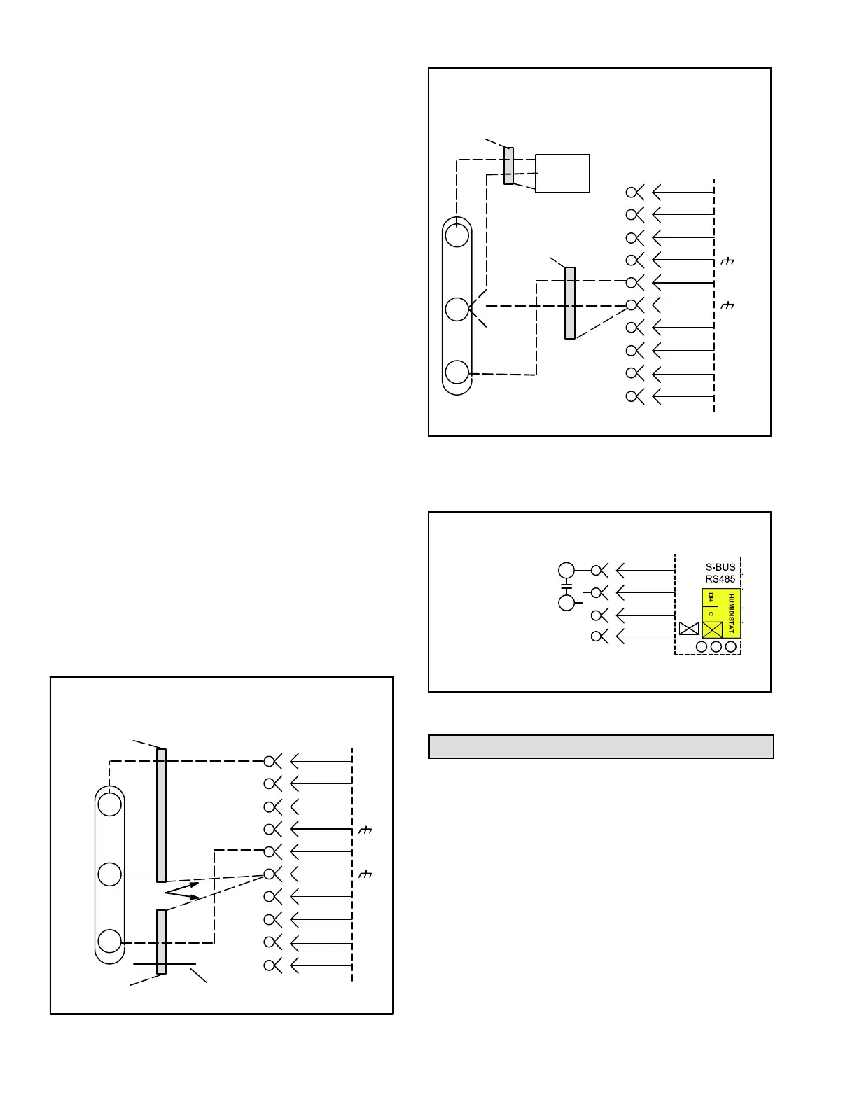
FIGURE 13
FIELD WIRING REHEAT UNITS
(Using A Dehumidification Switch)
7
10
8
9
R
DI−4
C
Use 24 VAC (R) from any terminal
available on P299−2, −5, or −7.
P299
DEHUMIDIFICATION
SWITCH
Blower Operation and Adjustments
Supply Air Staged Units - The blower rotation will
always be correct on units equipped with an inverter.
Checking blower rotation is not a valid method of
determining voltage phasing for incoming power.
Supply Air Staged Units and Units Equipped With
Optional Voltage or Phase Detection - The Unit
Controller checks the incoming power during start-up. If
the voltage or phase is incorrect, the Unit Controller will
display an alarm and the unit will not start.
A-Blower Operation
Refer to the Unit Controller Setup Guide to energize
blower. Use this mobile service app menu:
SERVICE > TEST > BLOWER
 Loading...