Page 51
508288-01 9/2022
240 & 300
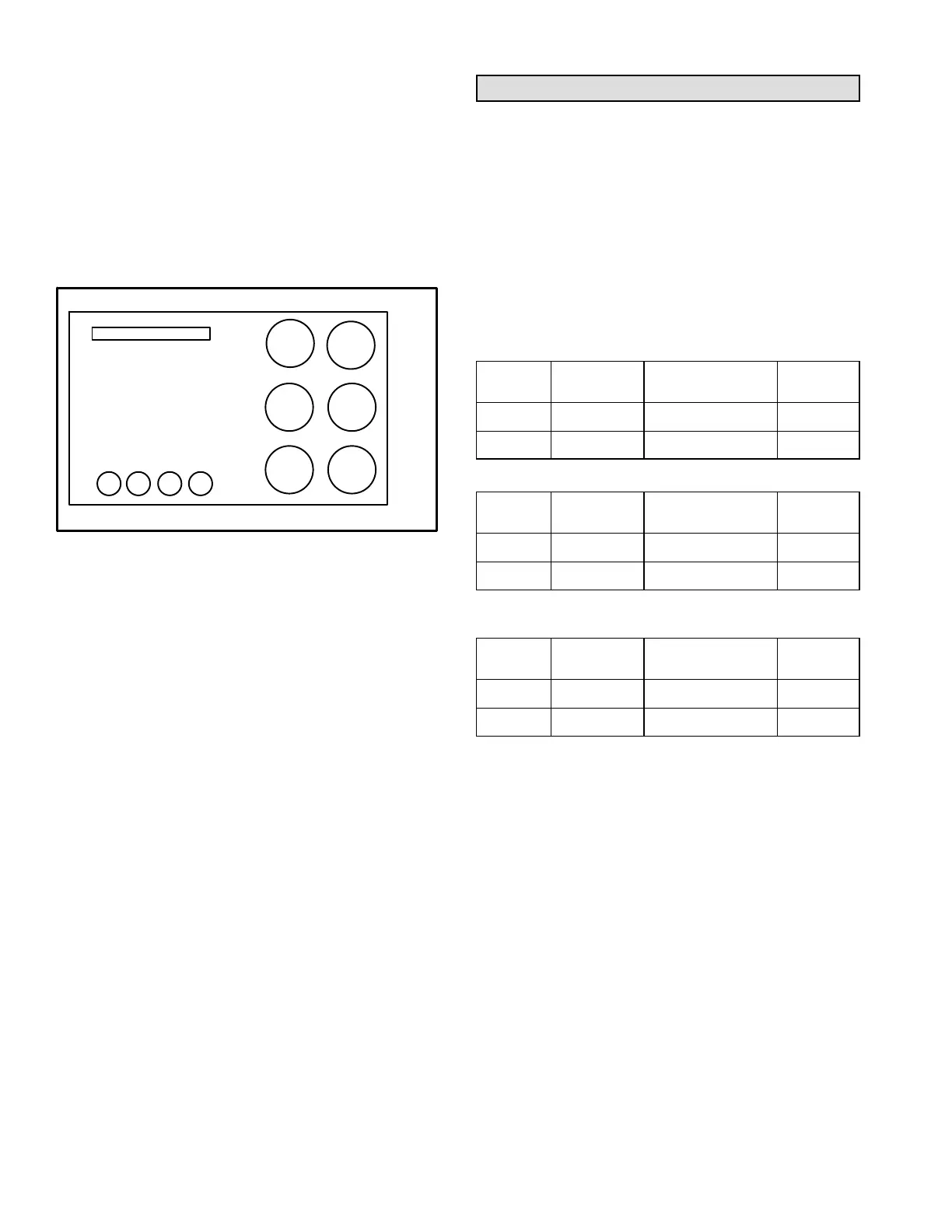
Condenser fans 1, 2, and 3 are energized when
compressor 1 or 2 are energized. As cooling demand
increases, all six condenser fans are energized. See
figure 24.
Condenser fans 1, 2, 4, and 5 are de-energized when
outdoor temperature drops below 62°F (17°C).
Condenser fans 3 & 6 modulate to maintain target
liquid temperatures when outdoor temperature drops
below 62°F (17°C).
240 & 300 CONDENSER FANS
FIGURE 24
COND.
FAN 5
COND.
FAN 4
COND.
FAN 1
COND.
FAN 2
COND.
FAN 6
COND.
FAN 3
12 3
COMPRESSORS
4
Prognostic Sensors
Temperature thermistor sensors (RT46-53) are located
on specific points for each refrigeration circuit.
Temperature thermistors provide continuous
temperature input to the unit controller for proper cooling
operation as well as system protection. Controller logic
will de-energize compressors for each refrigeration circuit
when evaporator coil temperature falls below 32°F (0°C)
to prevent evaporator freeze-up.
Each thermistor must be specifically placed for proper
unit operation and to initiate valid alarms. See table
14-16 for proper locations.
TABLE 14
LGT/LCT156
Cat. No.
Ass'y. No.
Sensor
Yellow, Blue
Figure
22J06 623049-01 RT46, 47 25
23V50 623049-05 RT48, 49 26
TABLE 15
LGT/LCT180
Cat. No.
Ass'y. No.
Sensor
Yellow, Blue, Red
Figure
22J06 623049-01 RT46, 47, 50 27
23V50 623049-05 RT48, 49, 52 28
TABLE 16
LGT/LCT210, 240, 300
Cat. No.
Ass'y. No.
Sensor
Yel, Blu, Red, Grn
Figure
22J06 623049-01 RT46, 47, 50, 51 29
23V50 623049-05 RT48, 49, 52, 53 30
 Loading...