Page 59
508288-01 9/2022
11- The ignition sequence will start.
12- If the appliance does not light the first time (gas line
not fully purged), it will attempt up to two more
ignitions before locking out.
13- If lockout occurs, repeat steps 1 through 10.
14- If the appliance will not operate, follow the
instructions “Turning Off Gas to Appliance” and call
your service technician or gas supplier.
Turning Off Gas to Unit
1- If using an electromechanical thermostat, set to the
lowest setting.
2- Before performing any service, turn off all electrical
power to the appliance.
3- Open or remove the heat section access panel.
4- Turn gas valve switch to OFF.
5- Close or replace the heat section access panel.
WARNING
Danger of explosion. Can cause injury or
death. Do not attempt to light manually.
Unit has a direct spark ignition system.
Heating Operation and Adjustments
(Gas Units)
A-Heating Sequence of Operation
1- On a heating demand the combustion air inducer
starts immediately.
2- Combustion air pressure switch proves inducer
operation. After a 30-second pre-purge, power is
allowed to ignition control. Switch is factory set and
requires no adjustment.
3- Spark ignitor energizes and gas valve solenoid
opens.
4- Spark ignites gas, ignition sensor proves the flame
and combustion continues.
5- If flame is not detected after first ignition trial, ignition
control will repeat steps 3 and 4 two more times
before locking out the gas valve.
6- For troubleshooting purposes, an ignition attempt
after lock out may be re-established manually. Move
thermostat to “OFF” and return thermostat switch to
“HEAT” position.
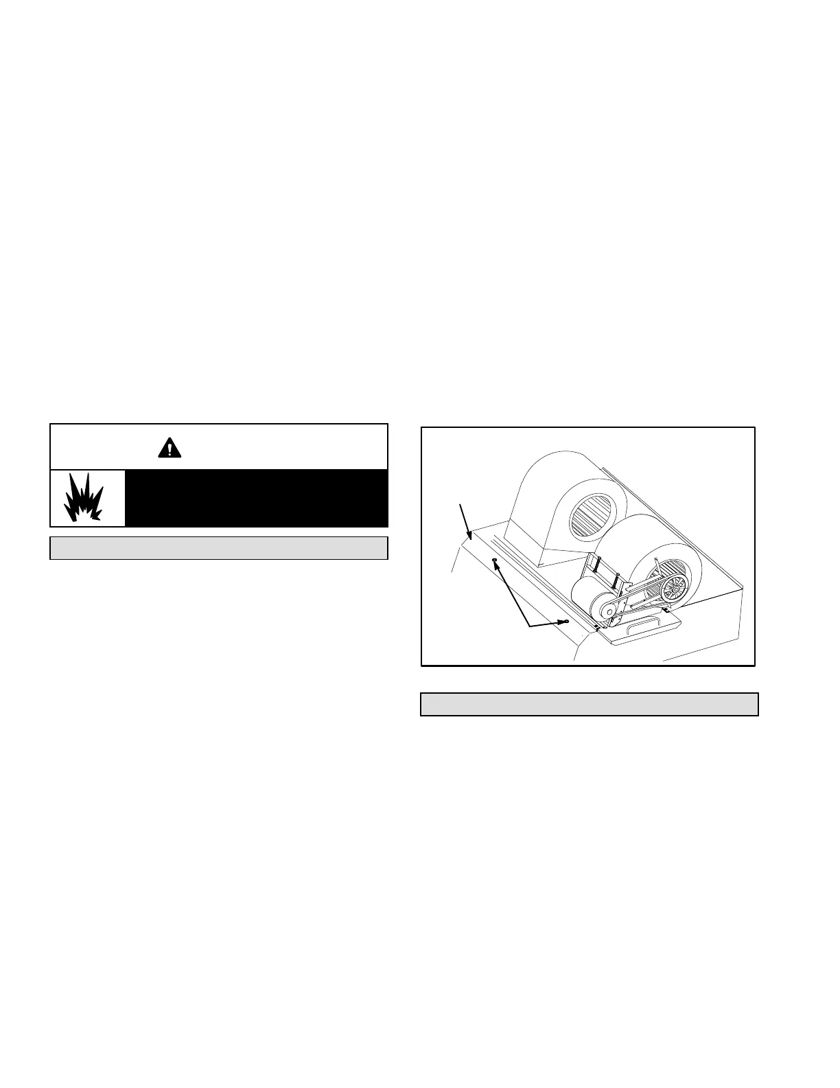
B-Limit Controls
Limit controls are factory-set and are not adjustable. Two
limits are located on the drip shield in the blower
compartment. See figure 32.
C-Heating Adjustment
Main burners are factory-set and do not require adjustment.
The following manifold pressures are listed on the gas valve.
Natural Gas Units - Low Fire - 1.6” w.c.
(not adjustable)
Natural Gas Units - High Fire - 3.7” w.c.
LP Gas Units - Low Fire - 5.5” w.c.
(not adjustable)
LP Gas Units - High Fire - 10.5” w.c.
LIMIT LOCATION
FIGURE 32
LIMITS
DRIP
SHIELD
Electric Heat Start-Up (LCT Units)
Factory- or Field-Installed Option
Electric heat will stage on and cycle with thermostat
demand. Number of stages of electric heat will vary
depending on electric heat assembly. See electric heat
wiring diagram on unit for sequence of operation.
 Loading...