Page 61
508288-01 9/2022
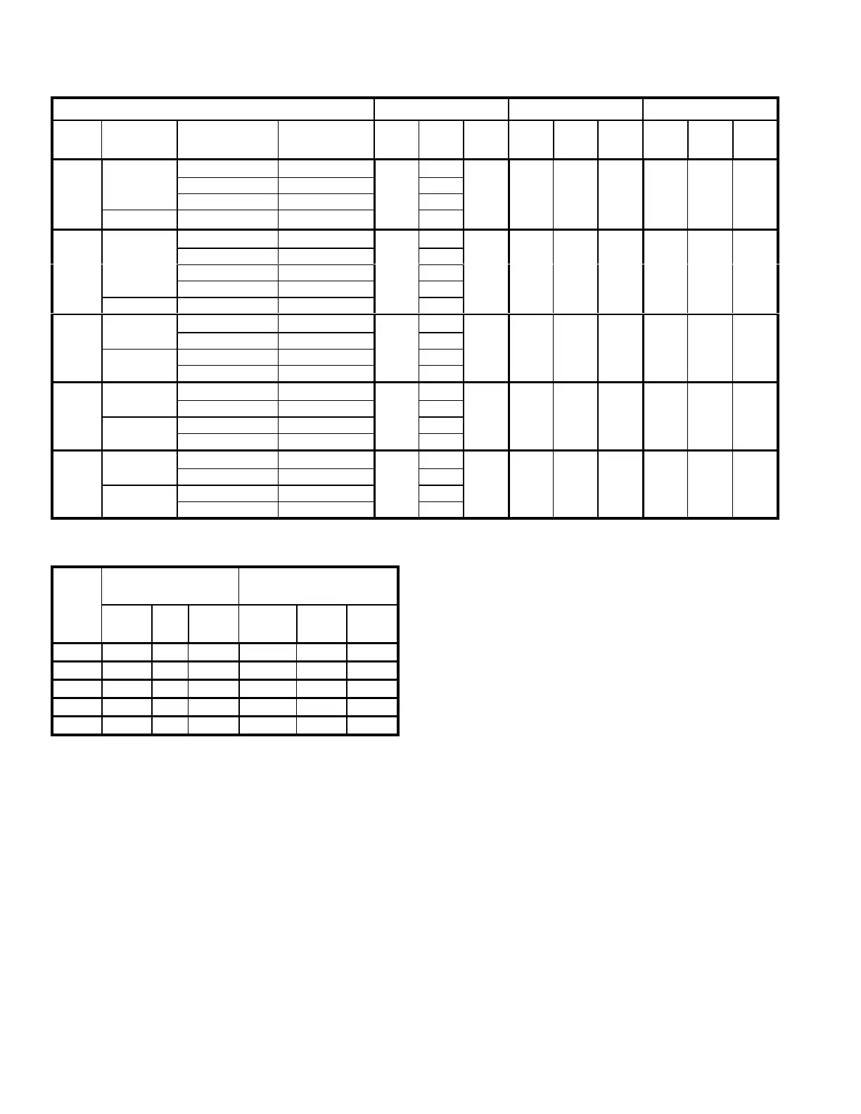
TABLE 18
HEATING, VENTILATION & SMOKE MINIMUM AND MAXIMUM CFM
Unit Heating CFM Vent CFM Smoke CFM
Tons Model Speed Heat Code
De
fault
Min Max
De
fault
Min Max
De
fault
Min Max
13
LGT156H
Low L 5200 2725 6250 5200 1950
5200 1950 6250
Std S 4325
Med M 4500
LGT156H
All N, E, J, K, L 5200
15 LGT180H Low L 6000 2725 7200 6000 2250 6000 2250 7200
Std S 4325
Med M 4500
High H 5125
LCT180H 15,30,45,60kW N, E, J, K, L 5200
17.5 LGT210H Low, Std, Med L, S, M 7000 4500 8400 7000 2625 7000 2625 8400
High H 5125
LCT210H 15,30,45,60kW N, E, J, K, L 5200
90kW P 6000
20 LGT240H Low, Std, Med L, S, M 8000 4500 9600 8000 3000 8000 3000 9600
High H 5125
LCT240H 15,30,45,60kW N, E, J, K, L 5200
90kW P 6000
25 LGT300S Low, Std, Med L, S, M 10000 4500 10000 3750 10000 3750 12000
High H 5125
LCT300S 15,30,45,60kW N, E, J, K, L 5200
90kW P 6000
*Use highest value between Heating and Cooling High CFM Max.
TABLE 19
COOLING MINIMUM AND MAXIMUM CFM
LGT/
LCT
Unit
Cool 1 CFM
Cooling Low CFM
Cool 4 CFM
Cooling High CFM
De
fault
Min Max Default Min Max
156H 3380 1500 6250 5200 4000 6250
180H 3900 2000 7200 5400 5000 7200
210H 4550 2500 8400 6300 6000 8400
240H 5200 3000 9600 7200 6250 9600
300S 6500 3500 12000 9000 7000 12000
*Use Cooling High CFM Max.
Set Minimum Position 2
Use the following mobile service app menu in the Unit
Controller to set “Min OCP Blwr Low” for the blower CFM
below the “midpoint” CFM. When navigating into this
menu, the Unit Controller will run damper calibration and
allow damper position adjustment.
RTU MENU > SETTINGS > RTU OPTIONS > DAMPER
Tap "Next" to skip tabs and complete damper position
calibration until "Damper Calibration Blower Speed High"
tab appears.
Measure the intake air CFM. If the CFM is lower than the
design specified CFM for ventilation air, use the Unit
Controller to increase the damper percent open. If the
CFM is higher than specified, decrease the damper
percent open.
Note - Intake air CFM can also be determined using the
outdoor air temperature, return air temperature and
mixed air temperature. Refer to the economizer or
outdoor air damper installation instructions.
E-Inverter Bypass Option
The supply air inverter is factory-set to by-pass the
inverter manually. To by-pass the inverter and operate the
blower in the constant air volume mode, use the following
Unit Controller menu and set to “engaged”:
SETTINGS > RTU OPTIONS > BLOWER > VFD
BYPASS
To configure the unit to by-pass the inverter automatically,
use the following Unit Controller menu.
SETUP > INSTALL
Press SAVE until the menu reads:
CONFIGURATION ID 1
Change the 6
th
character position to A for automatic
bypass option.
Press SAVE
Caution - Units not equipped with an inverter will have the
6
th
character set to N, indicating the inverter is not
bypassed. The blower motor could be damaged and/or
result in product or property damage if the setting is
changed to automatic or manual.
 Loading...