Page 18
LGH/LCH420, 480, 540, 600
Variable Air Volume Start-Up
Units may contain an optional supply air blower equipped
with a variable frequency drive A96 (VFD) which varies
supply air CFM.
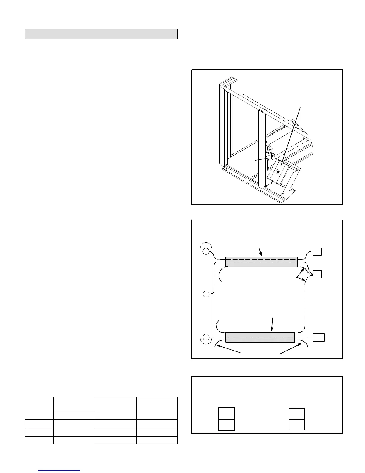
The supply air VFD (A96) is located near the compressors.
See figure 22.
A-Start-Up
1- A pressure transducer (A30) is shipped in a box in the
blower compartment. Install the transducer according
to manufacturer's instructions.
Note - Make sure the transducer is installed in the main duct
at least 2/3 of the distance away from the unit.
2- Two twisted pairs of shielded cable must be used to
connect the pressure transducer. See figure 23.
3- Open all zone dampers and/or boxes.
4- Locate the A55 Unit Controller in the control box.
5- Use the Unit Controller to calibrate the blower CFM.
Select the SETUP->TEST & BALANCE->BLOWER
menu to start the blower. The Unit Controller will
display the percent of blower speed. Adjust blower
speed percentage to meet design airflow
specifications. Allow blower speed to stabilize.
6- Press SAVE to display the current static pressure. If
the static pressure meets the design specification,
press SAVE again to set the setpoint. If the static
pressure does not meet the design specification,
adjust the pressure and press SAVE to set the
setpoint.
7- Record new setpoints in table 4.
Note - The Unit Controller will lock-out the unit for 5
minutes if static pressure exceeds 2.0”w.c. for 20
seconds. The Unit Controller will permanently shut down
the unit after three occurrences. See Unit Controller
parameters 110, 42, and 43 to adjust default values.
8- If the desired CFM cannot be met with current pulley
setup, refer to the Blower Operation and Adjustments
section to adjust CFM.
B-Unit Operation
Use the Unit Controller to check unit mechanical operation.
See the Service - Test section of the Unit Controller manual.
C-Supply Air VFD By-Pass Plug (Optional)
IMPORTANT - All dampers must be open to prevent
damage to duct work and dampers.
TABLE 4
RECORD ADJUSTED SETPOINTS
Parameter
Setpoint
Description
Setpoint
“w.c.
Display
Setting
386 Smoke
387 Ventilation
388 Heating
389 Cooling
The supply air VFD may be by-passed using jack/plug
connections. Locate J/P198 connectors in control box
area under the relays. Disconnect J198 from P198 and
connect J204 to P198. See figure 24. Blower will operate in
constant air volume mode.
FIGURE 22
SUPPLY AIR VARIABLE FREQUENCY DRIVE
SUPPLY AIR
VFD (A96)
OUTDOOR
AIR
SECTION
VIEW SHOWN
FROM FRONT
SIDE OF UNIT
OPTIONAL
A34
PRESSURE TRANSDUCER WIRING
TWISTED
PAIR
UNUSED WIRE
DRAIN
NOT
CONNECTED
NOT
CONNECTED
TWISTED
PAIR
FIGURE 23
UNIT
CONTROLLER
TB18
A30
9
6
26
+
_
+
TB24
FIGURE 24
SUPPLY AIR VFD BY-PASS CONNECTOR
CONNECTORS USED
FOR SUPPLY AIR
VFD OPERATION
CONNECTORS USED TO BY-PASS
VFD AND OPERATE SUPPLY AIR
BLOWER AT MAXIMUM SPEED
J198
P198
J204
P198
 Loading...


