Page 17
507232-04 7/2017
SETTINGS > RTU OPTIONS > EDIT PARAMETER >
ENTER DATA ID - 9 > MIN DAMPER LOW BLOWER =
X.X%
Measure the intake air CFM. If the CFM is lower than the
design specified CFM for ventilation air, use the Unit
Controller to increase the damper percent open. If the
CFM is higher than specified, decrease the damper
percent open.
Note - Intake air CFM can also be determined using the
outdoor air temperature, return air temperature and mixed
air temperature. Refer to the economizer or outdoor air
damper installation instructions.
Set Minimum Position 2
Use the same menu in the Unit Controller to set “Min OCP
Blwr High” for the blower CFM above the “midpoint” CFM.
When navigating into this menu, the Unit Controller will
bring on the corresponding blower speed and allow damper
position adjustment.
SETTINGS > RTU OPTIONS > DAMPER > MIN
DAMPER POSITION BLOWR ON HIGH = X.X%
Measure the intake air CFM. If the CFM is lower than the
design specified CFM for ventilation air, use the Unit
Controller to increase the damper percent open. If the CFM
is higher than specified, decrease the damper percent
open.
Note - Intake air CFM can also be determined using the
outdoor air temperature, return air temperature and mixed
air temperature. Refer to the economizer or outdoor air
damper installation instructions.
E-Inverter Bypass Option
The supply air inverter is factory-set to by-pass the inverter
manually. To by-pass the inverter and operate the blower in
the constant air volume mode, use the following Unit
Controller menu and set to “engaged”:
SETTINGS > RTU OPTIONS > BLOWER > VFD
BYPASS
To configure the unit to by-pass the inverter automatically,
use the following Unit Controller menu.
SETUP > INSTALL
Press SAVE until the menu reads:
CONFIGURATION ID 1
Change the 6
th
character position to A for automatic bypass
option.
Press SAVE
Caution - Units not equipped with an inverter will have the
6
th
character set to N, indicating the inverter is not
bypassed. The blower motor could be damaged and/or
result in product or property damage if the setting is
changed to automatic or manual.
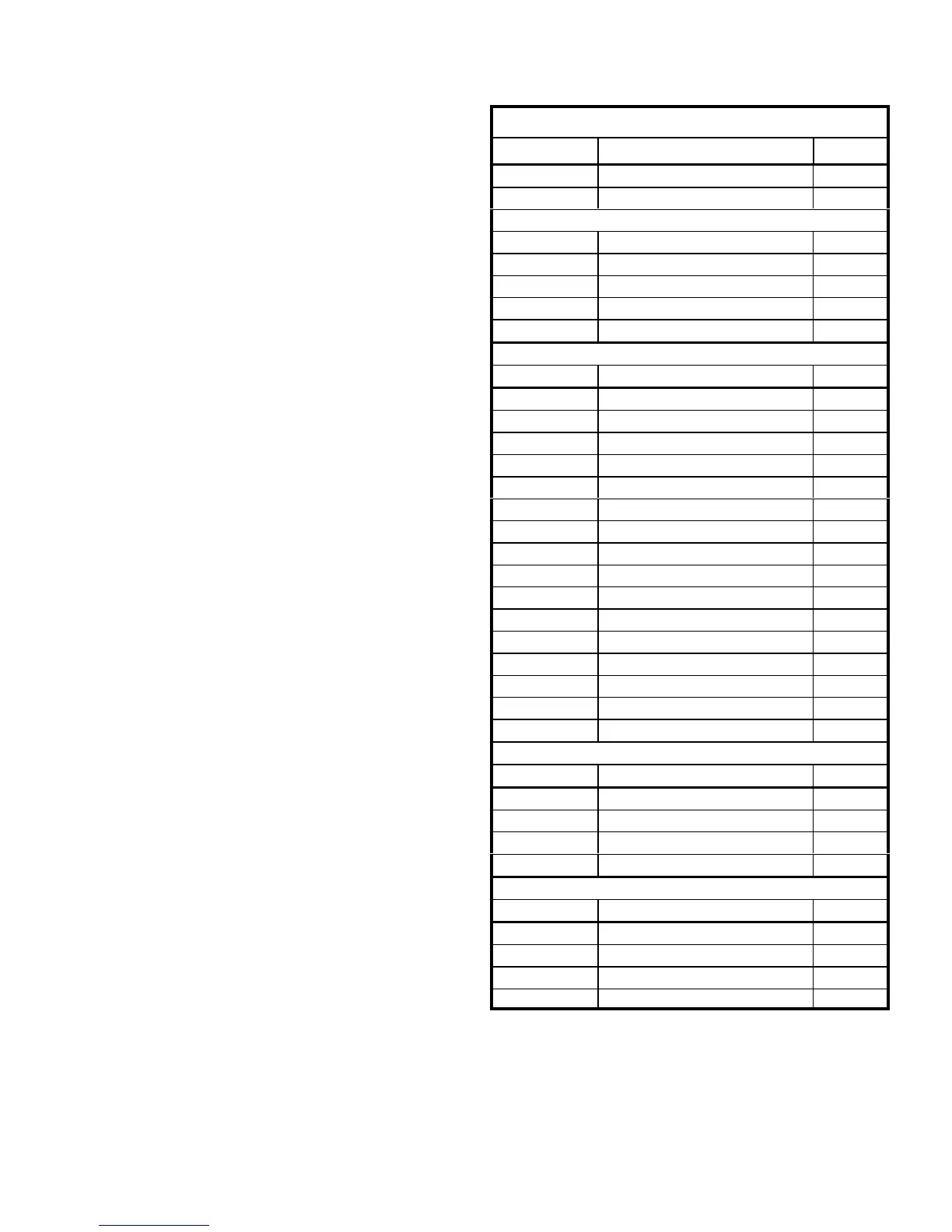
TABLE 3
MINIMUM AND MAXIMUM CFM - STAGED BLOWERS
Gas Heat Minimum CFM
Unit Gas Heat Size Airflow CFM
LGH420-600 Std, Std Mod 9300
LGH420-600 High, High Mod 10800
Electric Heat Minimum CFM
Unit Heat Size (kw) Airflow CFM
LCH420 All 9800
LCH480 All 11200
LCH540 All 12600
LCH600 All 14000
Cooling minimum CFM
Unit Blower Speed Airflow CFM
LGH/LCH420 Cool 1; Clg. Low 5600
Cool 2; Clg. Med. Low 5600
Cool 3; Clg. Med. High 5600
Cool 4; Clg. High 9800
LGH/LCH480 Cool 1; Clg. Low 6400
Cool 2; Clg. Med. Low 6400
Cool 3; Clg. Med. High 6400
Cool 4; Clg. High 11200
LGH/LCH540 Cool 1; Clg. Low 7200
Cool 2; Clg. Med. Low 7200
Cool 3; Clg. Med. High 7200
Cool 4; Clg. High 12600
LGH/LCH600 Cool 1; Clg. Low 8000
Cool 2; Clg. Med. Low 8000
Cool 3; Clg. Med. High 8000
Cool 4; Clg. High 14000
Smoke and Ventilation Minimum CFM
Unit Not Applicable Airflow CFM
LGH/LCH420 NA 5250
LGH/LCH480 NA 6000
LGH/LCH540 NA 6750
LGH/LCH600 NA 7500
Heating and Cooling Maximum CFM
Unit Blower Speed Airflow CFM
LGH/LCH420 High 16800
LGH/LCH480 High 19200
LGH/LCH540 High 21600
LGH/LCH600 High 24000

 Loading...