Page 58
LGH/LCH420, 480, 540, 600
Optional Outdoor Air CFM Control
Outdoor air CFM Control is a factory-installed option
available on units equipped with a supply air variable
frequency drive (VFD) and economizer.
The Unit Controller modulates outdoor air dampers to
maintain a constant amount of outdoor air regardless of
blower speed. This ensures minimum ventilation
requirements are met at lower supply air volumes.
The Unit Controller uses a velocity sensor (A24) to
modulate dampers. The sensor is located in the outdoor air
stream. See figure 53.
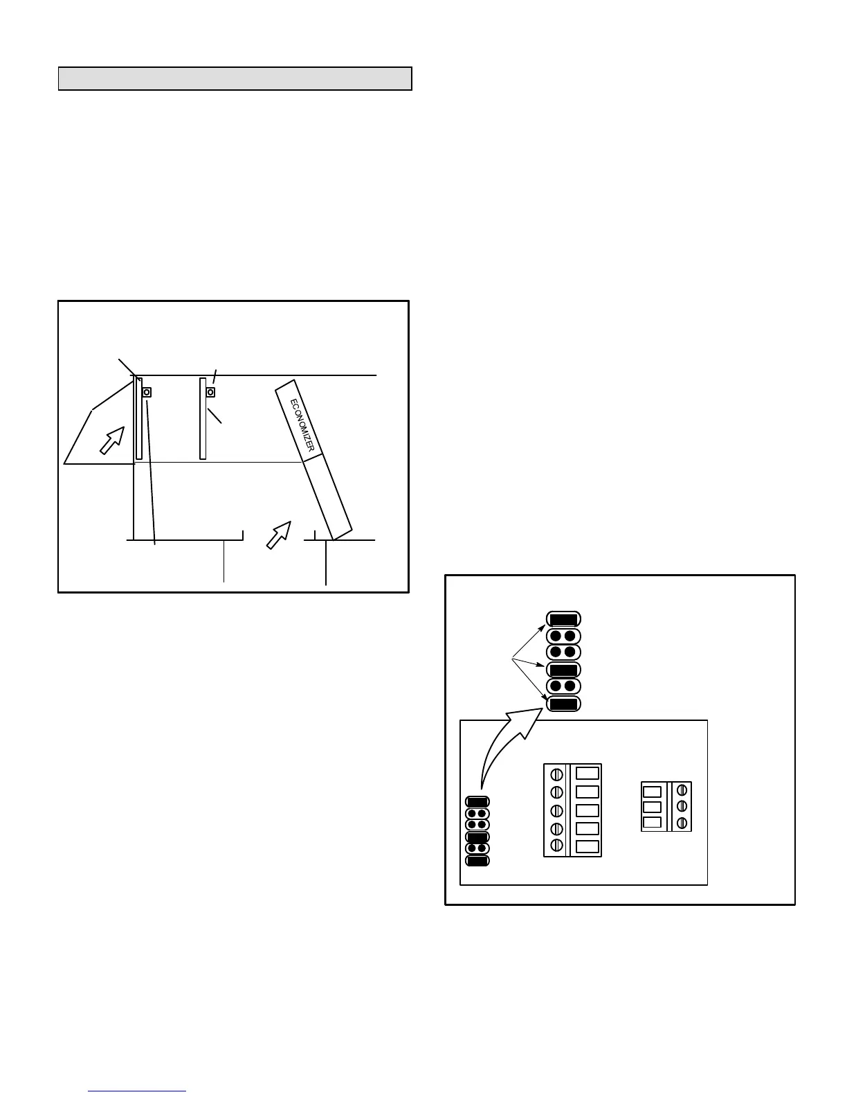
FIGURE 53
VELOCITY SENSOR LOCATION
RETURN AIR
OUTDOOR
AIR
SENSOR LOCATION IN
DOWNFLOW DIS
CHARGE APPLICATIONS
SENSOR LOCATION IN
HORIZONTAL DISCHARGE
APPLICATIONS
DOWNFLOW
OA FILTER
HORIZONTAL
OA FILTER
Configuration ID Setting
1- Enable the Outdoor Air Control feature and set the
velocity sensor range using the M3 Unit Controller
SETUP > INSTALL menu. Navigate to Configuration
ID 1. Set position 8 to:
H Outdoor air control installed with A24 control set for
high range (0-1968ft/min)
2- Make sure the A24 jumper is installed in the low range
position as shown in figure 54.
3- Operate the blower in high speed and adjust the
minimum damper position. Use SETUP > TEST &
BALANCE > DAMPER > MIN DAMPER POSITION
menu. Adjust minimum damper position and press
SAVE. The Unit Controller will automatically save and
display the velocity setpoint. Press SAVE again to
confirm.
Note - The minimum damper position setting MUST be set
lower than the OAC max damper position setting (50%
default). To modify the max damper position setting,
navigate to SETTINGS > EDIT PARAMETERS and select
parameter 117 (DCV MAX DAMPER OPEN).
Additional outdoor air CFM control settings are available.
See parameters 117 and 134 in the Unit Controller manual.
Make adjustments through the SETTINGS > EDIT
PARAMETERS menu; select the required parameter.
4- Replace A24 control cover.
NOTE - Refer to local codes or authorities having
jurisdiction when determining design minimum outdoor air
requirements.
Velocity Sensor Settings
The A24 control is factory-set for 0-10m/s. (0-1968ft/min.)
Note - The configuration ID velocity range must be set to "H"
and the jumper setting on the A24 control must be set at low
range. No other combinations may be used with the
100501-02 sensor.
The jumper is factory-set at low range (0-1968ft/min).
Note - The configuration ID velocity range must be the same
as the jumper setting on the A24 control. The jumper is
factory-set at low range (0-1968ft/min).
VELOCITY SENSOR (A24) JUMPER SETTINGS
FIGURE 54
V+
GND
AV
0-10m/s (0-1968ft/min.)
24VAC
Common
Airflow Output
(0-10VDC)
1
2
3
JUMPERS
t90
HI
MED
LO
I
U
t90
HI
MED
LO
I
U
Sets respond time to 4 sec.
Sets output signal to voltage
 Loading...