Page 16
LGH/LCH420, 480, 540, 600
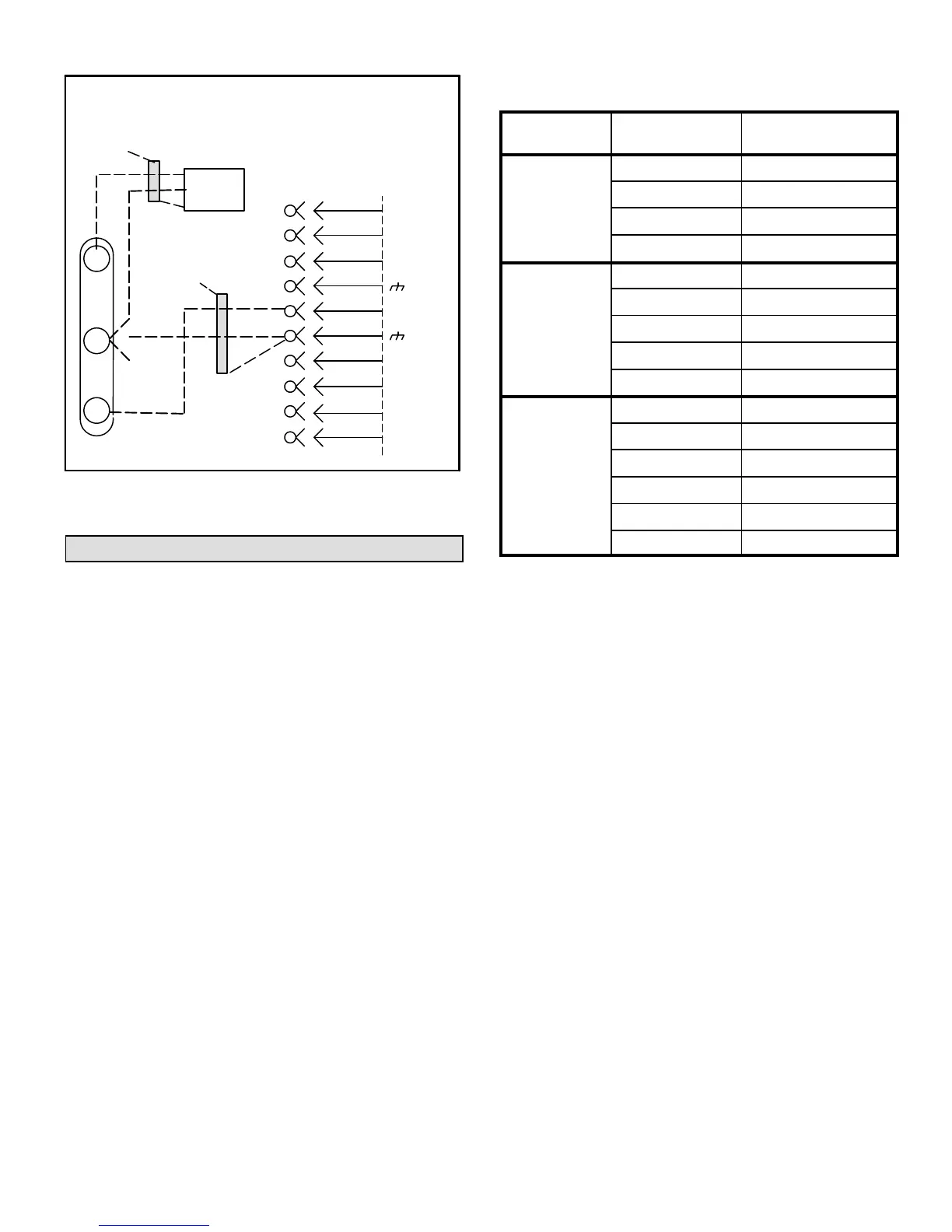
FIGURE 21
FIELD WIRING HOT GAS REHEAT UNITS
(Using A Humidity Sensor With More
Than 150 Ft. Wire Runs)
ISOLATED 24V
TRANSFORMER
9
8
P298
J298A
1
2
B
3
4
C
5
6
7
D
10
A91
VIN
VO
GND
R
C
AI-1
HUM
TMP
DO-1
C
DI-1
DO-2
NOT
CONNECTED
NOT
CONNECTED
DRAIN
A55 UNIT
CONTROLLER
Multi-Staged Air Volume Start-Up
A-Design Specifications
Use table 2 to fill in field-provided, design specified blower
CFM for appropriate unit.
If only high and low cooling design specifications are
provided, set the medium cooling CFM at the high or low
cooling design spec or any CFM between.
B-Set Maximum CFM
Use table 2 to determine highest blower CFM for
appropriate unit. Adjust the blower pulley to deliver that
amount of CFM with only the blower operating. See
Determining Unit CFM in the Blower Operation and
Adjustment section.
C-Set Blower Speeds
1-Use the following menu to enter the blower design
specified CFM into the Unit Controller. Make sure
blower CFM is within limitations shown in table 3. Refer
to the Unit Controller manual provided with unit.
SETUP > TEST & BALANCE > BLOWER >
2-Enter the following design specifications as shown in
table 2.
Blower / Heat CFM
Cooling High CFM
1
Cooling Low CFM
1
Vent CFM
TABLE 2
Blower CFM Design Specifications
No. Stages /
Control Type
Blower Speed
1
Design
Specified CFM
2 Stages /
Thermostat
Htg.
Clg. High
Clg. Low
Ventilation
3 Stages /
Thermostat
2
Htg.
Clg. High
Clg. Med.
Clg. Low
Ventilation
4 Stages /
Room Sensor
OR
Discharge Air
Control
Htg.
Clg. High
Clg. Med. High
Clg. Med. Low
Clg. Low
Ventilation
1
Available blower speeds vary by unit and thermostat stages.
2
Requires a transfer relay (K27) and three-stage thermostat.
3-Adjust the blower RPM to deliver the target CFM based
on the measured static pressure using the blower table.
4-Measure the static pressure again and apply the static
pressure and RPM to the blower tables to determine
adjusted CFM.
5-Repeat adjustments until design CFM is reached.
1
The Unit Controller will prompt when more cooling stages
are available depending on the number of compressors and
the control mode.
2
Requires a transfer relay (K27) and three-stage thermostat.
D-Set Damper Minimum Position
To maintain required minimum ventilation air volumes when
the unit is in the occupied mode, two minimum damper
positions must be set. The Unit Controller will open the
dampers to “Min OCP Blwr Low” when blower CFM is
BELOW a “midpoint” CFM. The Unit Controller will open the
damper to “Min OCP Blwr High” when blower CFM is at or
ABOVE the “midpoint” CFM.
The Unit Controller will calculate the “midpoint” CFM.
Set Minimum Position 1
Use the following menu in the Unit Controller to set “Min
OCP Blwr Low” for the blower CFM below the “midpoint”
CFM. When navigating into this menu, the Unit Controller
will bring on the corresponding blower speed and allow
damper position adjustment.

 Loading...