Page 15
507232-04 7/2017
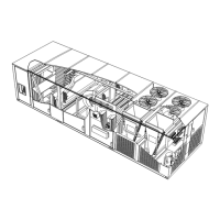
3- Third-Party Zoning -
The Unit Controller will operate up to four stages of
heating and cooling based on a third-party zoning
system. Only 4 digital inputs are required to control
the rooftop unit: G (blower enable), OCP (occupied),
Y1 (enables discharge cooling) and W1 (enables
discharge heating). Make wiring connections as
shown in figure 19.
24 VOLT FIELD WIRING
FOR UNITS WITH SUPPLY AIR VFD
FIGURE 19
RTU w/Unit
Controller
TB18
Supply Static Pr.
Sensor (A30)
Heating Demand
Cooling Demand
Occupied Demand
Ventilation Demand
3
rd
Party
Zoning
Control
System
24VAC Digital Signals
G
O
Y1
W1
Optional Building Static Pressure
Switch(s) (S37,S39) or Sensor (A34)
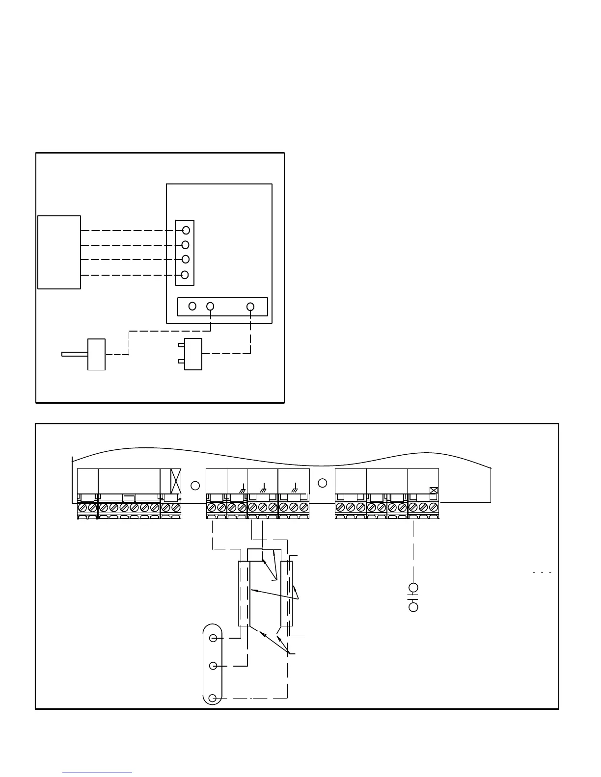
D-Hot Gas Reheat Units Only -
Install humidity sensor in accordance with instructions
provided with sensor. A DDC input may be used to initiate
dehumidification instead of a sensor. Make wiring
connections as shown in figure 17 for Thermostat Mode
and figure 18 for Zone Sensor Mode. In addition, connect
either a zone sensor or a dehumidification input as shown
in figure 20.
Humidity Sensor Cable Applications:
Wire runs of 50 feet (mm) or less:
Use two separate shielded cables containing 20AWG
minimum, twisted pair conductors with overall shield.
Belden type 8762 or 88760 (plenum) or equivalent.
Connect both cable shield drain wires to TB1-7 as shown in
figure 20.
Wire runs of 150 feet (mm) or less:
Use two separate shielded cables containing 18AWG
minimum, twisted pair conductors with overall shield.
Belden type 8760 or 88760 (plenum) or equivalent.
Connect both cable shield drain wires to TB1-7 as shown in
figure 20.
Wire runs over 150 feet (mm):
Use a local, isolated 24VAC transformer such as Lennox cat
#18M13 (20VA minimum) to supply power to RH sensor as
shown in figure 21. Use two shielded cables containing
20AWG minimum, twisted pair conductors with overall
shield. Belden type 8762 or 88760 (plenum) or equivalent.
FIGURE 20
Install optional A42
Phase Monitor and/or
S149 Overflow Control
HUMIDISTAT
INPUTSSMOKE
G24VAC
THERMOSTAT
R C
W1
G
W2
Y2
Y1
O
L
24VAC
RRC R
C
DI1
DI4
DI2
DI3
UNIT CONTROLLER
DRAIN
NOT CONNECTED
A91
HUMIDITY
SENSOR
VOUT
GND
VIN
ENERGY MANAGEMENT SYSTEM
DEHUMIDIFICATION SWITCH
TWISTED
PAIR
UNUSED
WIRE
24 VOLT FIELD WIRING HOT GAS REHEAT UNITS
(Using A Humidity Sensor With Less Than 150 Ft. Wire Runs)
OUTPUTSSENSOR
24VAC
IAQ
D01
TMP
D02
CR AI1 HUM
O
CCC
P
 Loading...