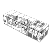
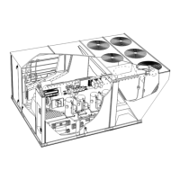
Page 14
LGH/LCH420, 480, 540, 600
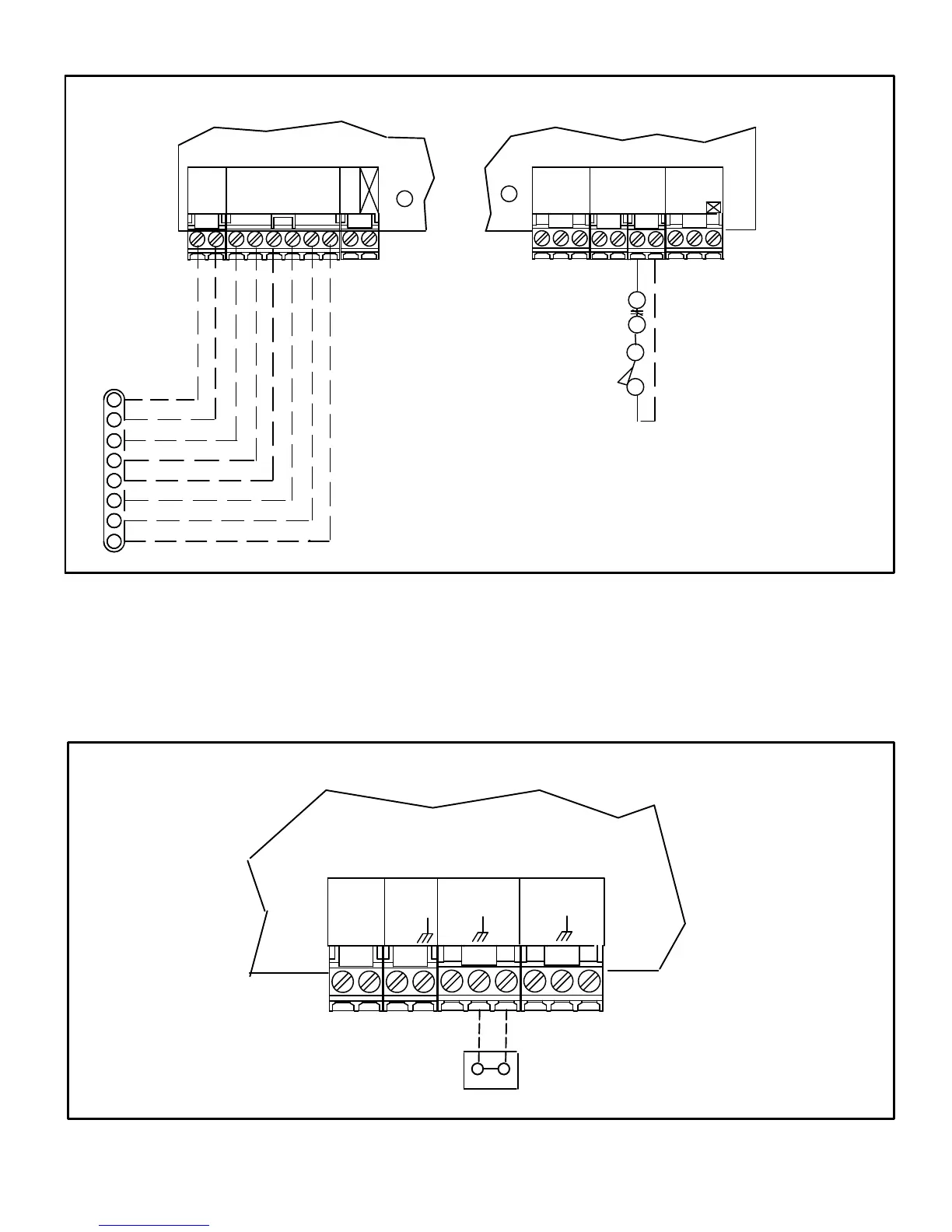
FIGURE 17
24 VOLT FIELD WIRING IN THERMOSTAT MODE
(Unit Controller in default T'Stat System Mode 6.01 Option 0)
Install optional A42
Phase Monitor and/or
S149 Overflow Control
INPUTSSMOKE
24VAC
RRC R
C
R
O
C
G
W1
W2
Y1
Y2
DI1
DI4
DI2 DI3
Not all terminals
are provided on
all thermostats.
2A2 (2HT/2C)
THERMOSTAT
NOTE - ON ELECTRO-ME
CHANICAL THERMOSTATS SET
ANTICIPATOR AT 0.1 AMPS.
UNIT CONTROLLER
C
G
W1 W2 Y1 Y2
O
THERMOSTAT
24
VAC
R
G
L
O
HUMIDISTAT
UNIT CONTROLLER
CP
2- Zone Sensor Mode -
The Unit Controller will operate up to four stages of
heating and cooling based on the Unit Controller
internal setpoints and the temperature from the A2
zone sensor. An optional Network Control Panel (NCP)
can also be used to provide setpoints. A thermostat or
return air sensor can be used as a back-up mode. See
figure 18 for field wiring.
Note - Install sensor and make communication wiring
connections as shown in literature provided with sensor.
A2 SENSOR
OUTPUTS
SENSOR
SENSOR
24VAC
RC
IAQ
HUM
AI1
D01
TMP
D02
UNIT CONTROLLER
FIGURE 18
24 VOLT FIELD WIRING IN ZONE SENSOR MODE
(Unit Controller in Zone Sensor Mode)

 Loading...