Page 45
507232-04 7/2017
Step 5. ALL TEMPERATURE MODES OF OPERATION
In the Economizer – Temperature mode, the damper opens
for free cooling when the outdoor air temperature is:
Less than return air temperature by at least a difference
of (Parameter 161 - ECON FRCL TMP OFFST) if
Temperature Offset mode is selected
Less than (Parameter 160 - ECON FREECL TEMP SP)
In all modes, dampers will try to modulate discharge air
temperature (RT6) to (Parameter 159 - FREE COOL
SUPPLY SP) which has a default setting of 55.0°F (13°C).
Refer to the “Displaying Sensor Inputs" section to read
return air (RT16) and outdoor air (RT17) temperatures. If
outdoor air is not cooler than return air, simulate a colder
outdoor air temperature with a resistor. Select a resistor
value that corresponds to a temperature (see table 21):
A Locate RT17 sensor in unit. Disconnect 1/4" quick
connect terminals on wires leading from sensor.
B Jumper RT17 wires leading back to control with the
appropriate resistor.
C Check all connections and wiring between RT17 and
the M3 Unit Controller, and between RT16 and the M3
Unit Controller.
TABLE 21
TMP MODE RESISTOR VALUES
Temp.
°F
(°C)
Size
Resist
or
Temp
. °F
(°C)
Size
Resist
or
Temp
. °F
(°C)
Size
Resist
or
Temp
. °F
(°C)
Size
Resist
or
30
(-1)
34,56
6
50
(10)
19,90
4
70
(21)
11,88
4
90
(32)
7,332
40 (
4)
26,10
6
60
(16)
15,31
3
80
(27)
9,298 100
(38)
5,826
Step 6. GLOBAL MODULATING (GLO) MODE OF
OPERATION
In the GLO (modulating) mode, dampers modulate open for
free cooling when the global input is energized; dampers
will try to modulate discharge air temperature (RT6) to
(Parameter 159 - FREE COOL SUPPLY SP) which has a
default setting of 55.0°F (13°C).
NOTE - The global input turns on the blower.
A Set global mode using the Configuration ID 1,
position 2, and set to character G.
B Connect a jumper between A55_P297-1 (24VAC) and
A55_P297-9 (global). The blower will be energized and
the damper will slowly open if discharge air temperature
(RT6) is greater than (Parameter 159 - FREE COOL
SUPPLY SP) which has a default setting of 55.0°F
(13°C).
C Disconnect 24VAC to A55_P297-9. The blower will turn
off and the damper will close.
D If the damper does not actuate check all connections
and wiring between P262A and B.
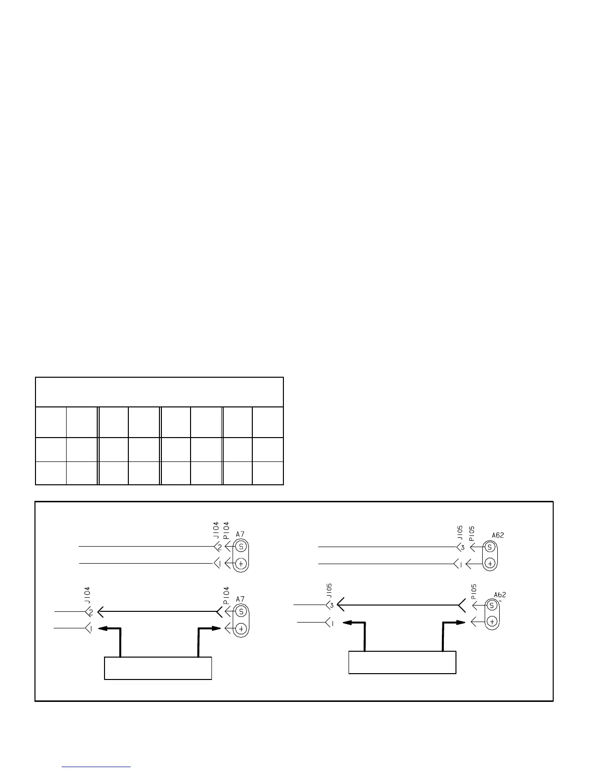
Step 7. ENTHALPY SENSOR OPERATION (A7 and
A62)
A Connect a direct current ammeter as shown in figure 39
to measure current output of A7 or A62.
NOTE - If Enthalpy Sensors are configured, current sensor
reading by M3 controller can be verified on User interface:
B The reading will be between 4 and 20 ma. depending on
outdoor temperature and humidity. Refer to figure 37 to
approximate reading.
Go to DATA > IN/OUTPUTS > SENSORS > LOCAL
(scroll down to IE: x.x mA and OE: x.x mA)
C If the meter reads zero, check sensor wiring harness for
continuity and/or check polarity of sensor wiring.
DISCONNECT J/P104
PLACE JUMPER WIRE HERE
READ
CURRENT
HERE
DC AMMETER
-
+
Damper Travel: % of Maximum Open
DISCONNECT J/P105
PLACE JUMPER WIRE HERE
READ
CURRENT
HERE
DC AMMETER
-
+
Measure A62 Current in SeriesMeasure A7 Current in Series
MEASURE A7 AND A62 CURRENT IN SERIES
FIGURE 39
 Loading...