Page 31
C-Adjusting Unit CFM
The supply CFM can be adjusted by changing Unit Con-
settings. Record any CFM changes on the parameter set-
tings label located on the inside of the compressor access
panel.
CAUTION
The BLOWER CALIBRATION process starts the
indoor blower at operational speeds and moves
the economizer damper blades. Before starting this
process, replace any access panels and close all
unit doors except compressor compartment door.
Blower calibration is required only on units that are newly
after installation. Use the mobile service app to navigate
-
ter the new CFM values are entered, select START CAL-
IBRATION. The blower calibration status is displayed as
a % complete. Upon successful completion, the mobile
service app will display CALIBRATION SUCCESS and go
back to the blower calibration screen.
IMPORTANT - The default value for Cooling Low CFM is
lower than a traditional singe- or two-speed blower. If op-
erating the unit with a 2- or 3-stage controller (2- or 3-stage
thermostat, DDC controller, etc.), it is recommended to in-
crease the Cooling Low CFM default value to a suitable
level for part load cooling (typically 60% of full load CFM).
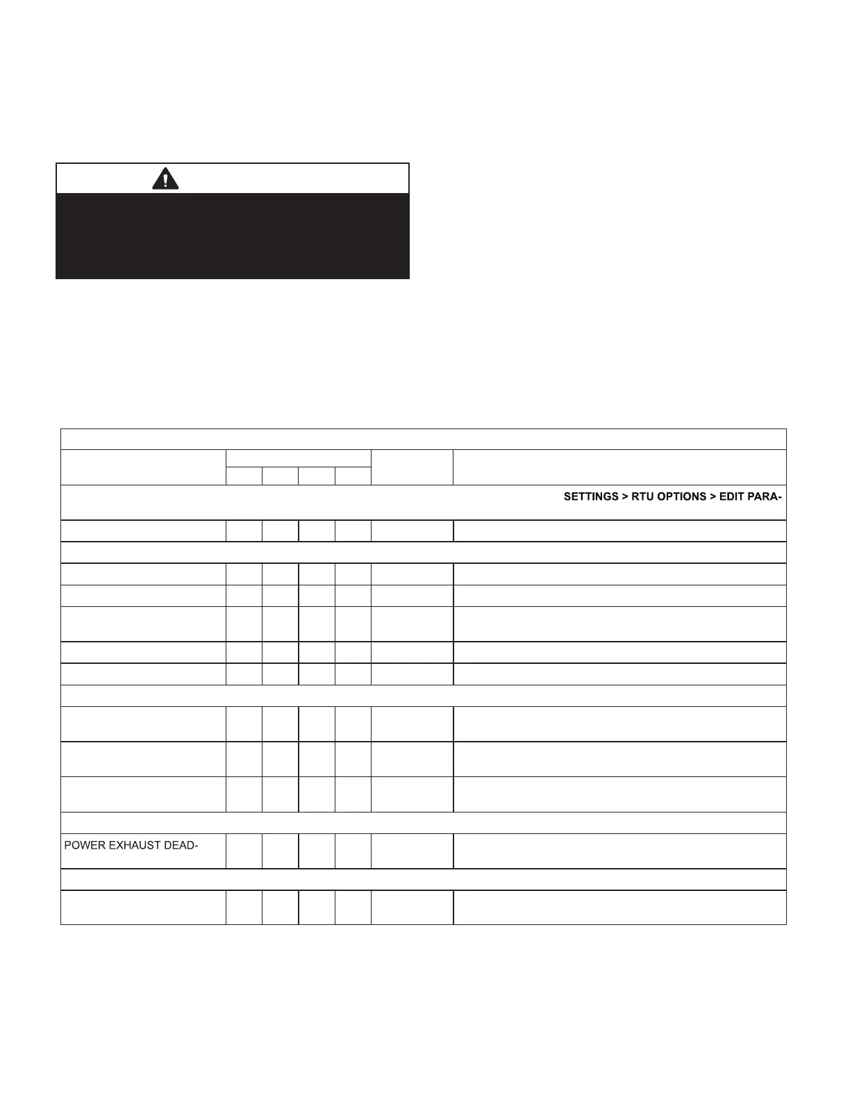
TABLE 5
036, 048, 060, 074U DIRECT DRIVE PARAMETER SETTINGS
LGM/LCH036-074U4E Default Parameter Settings
Parameter
Factory Setting
Field
Setting
Description
036 048 060 074
Note: Any changes to Smoke CFM setting must be adjusted before the other CFM settings. Use
METERS = 12
BLOWER SMOKE CFM 1200 1600 2000 2400 CFM Smoke blower speed
SETUP > TEST & BALANCE > BLOWER
BLOWER HEATING HIGH CFM 1200 1600 2000 2000 CFM High heat blower speed
BLOWER HEATING LOW CFM N/A 1250 1250 1250 CFM Low heat blower speed (applies to 150kBtuh 4-stg. gas heat only)
BLOWER COOLING HIGH
CFM
1100 1450 1825 2200 CFM High cooling blower speed
BLOWER COOLING LOW CFM 575 750 950 950 CFM Low cooling blower speed
BLOWER VENTILATION CFM 575 750 950 1150 CFM Ventilation blower speed
SETUP > TEST & BALANCE > DAMPER
BLOWER HIGH CFM DAMPER
POS %
0% 0% 0% 0% % Minimum damper position for high speed blower operation.
BLOWER LOW CFM DAMPER
POS %
0% 0% 0% 0% % Minimum damper position for low speed blower operation.
POWER EXHAUST DAMPER
POS %
50% 50% 50% 50% % Minimum damper position for power exhaust operation.
SETTINGS > RTU OPTIONS > EDIT PARAMETERS = 216
BAND %
10% 10% 10% 10% % Deadband % for power exhaust operation.
SETTINGS > RTU OPTIONS > EDIT PARAMETER = 10 (Applies to Thermostat Mode ONLY)
FREE COOLING STAGE-UP
DELAY
300
sec.
300
sec.
300
sec.
300
sec.
sec
Number of seconds to hold indoor blower at low speed before
switching to indoor blower at high speed.
Installer: Circle applicable unit model number and record any parameter changes under “Field Setting” column. Settings need to be recorded by
installer for use when Unit Controller is replaced or reprogrammed.
 Loading...


