Page 15
J386 J387 J388 J389 J390 J391 J392 J393
J395
J394
MODBUS
J413
LONTalk
Module
24VAC
Gnd
S−BUS SmartWire
System J304
Humidistat
Digital
Inputs
Smoke
24VAC
Gnd
24VAC
Thermostat
Service Relays
R + C
Spare
Analog
Inputs
Room
and RH
Sensors
Sensor
IAQ
TX
J358
Duct Sensor
J378
4−Character Seven
Segment LED
J379
J380
J381
J382
J383
J385
J384
J298
J297
J299
Sensor
IAQ
A11
HUM TMP
Sensor
Inputs
A12 C R
White Push
Button
Black Push
Button
Service Relays
P5
S−BUS
Factory Te st
P2 Expansion
Card Connection
(C4)
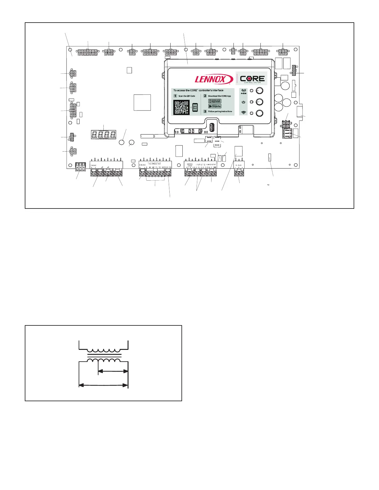
CORE Unit Controller (A55)
Wireless Control (W4)
FIGURE 3
I-UNIT COMPONENTS
All 3 through 6 ton (7 through 21 kW) units are congure to
order units (CTO). The LGM unit components are shown
in gure 1. All units come standard with hinged unit pan-
els. All L1, L2, and L3 wiring is color coded; L1 is red, L2
is yellow, and L3 is blue.
A-Control Box Components
LGM control box components are shown in gure 2. The
control box is located in the upper right portion of the com-
pressor compartment.
1-Control Transformers T1/T43
PINK
GRAY
ORANGE BLACK
230 VOLTS
208 VOLTS
PRIMARY
SECONDARY
FIGURE 4
All use a single line voltage to 24VAC transformer mount-
ed on the hinged control panel. Transformer supplies pow-
er to control circuits in the unit. The transformer is rated at
70VA and is protected by a 3.5 amp circuit (CB8).
The 208/230 (Y) voltage transformers use two primary
voltage taps as shown in gure 4, while the 460 (G) volt-
age transformer use a single primary voltage tap. T43 is
used for units with hot gas reheat for additional 24VAC.
2-Transformer T4 (J voltage)
All J volt units are equipped with a line voltage to 460V
3-phase transformer to power the indoor blower motor. T4
is mounted in the back panel of the compressor section
above T5.
3-Transformer T5 (G and J voltage)
All units use transformer T5 mounted in the back panel
in the compressor section. T5 is a line voltage to 230V
transformer to power the combustion air inducer, outdoor
fan motor, and optional UVC light ballast.. It is connected
to line voltage and is powered at all times.
4-Unit Controller A55 (Figure 3)
The Unit Controller provides all unit control functions, unit
status information, unit diagnostics, programmable pa-
rameters, and USB verication and prole sharing. The
unit controller can only be interfaced with via the CORE
Service mobile app. Refer to the Unit controller instruc-
tions provided for additional details on pairing and app
functions

 Loading...

