Page 36
TABLE 11
Input Rate Seconds Natuarl Seconds LP/Propane
138
34 86
24 60
6-Heat Exchanger
To Access or Remove Heat Exchanger From Unit:
1 -
2 - Remove access panel(s) and unit center mullion.
3 - Remove gas valve, manifold assembly and burners.
4 - Remove combustion air inducer. Pay careful
are removed.
Support heat exchanger (to prevent it from falling
6 - Remove screws supporting heat exchanger.
7 - To install heat exchanger, reverse procedure. Be
sure to secure all wires and check plumbing and
burner plate for airtight seal. Screws must be
7-Flame Sensing
Flame current is an electrical current which passes from
the ignition control through the sensor electrode during unit
operation. The current passes from the sensor through the
-
trode) to complete a safety circuit. The electrodes should
be located so the tips are at least 1/2” (12.7 mm) inside
NOTE-Electrodes are not eld adjustable. Any alterations
to the electrode may create a hazardous condition that
can cause property or personal injury.
1 - Disconnect power to unit.
2 - Remove lead from sensing electrode and install
sensing electrode and the sensing lead.
3 - Reconnect power and adjust thermostat for heating
demand.
4 -
Drop out signal is .09 or less.
Disconnect power to unit before disconnecting
meter. Make sure sensor wire is securely
reconnected before reconnecting power to unit.
NOTE-If the meter scale reads 0, the leads are
reversed. Disconnect power and reconnect leads
for proper polarity.
B-Cooling System Service Checks
LGM units are factory charged and require no further ad-
however, charge should be checked periodically using the
approach method. The approach method compares actual
liquid temperature with the outdoor ambient temperature.
See section IV- CHARGING.
NOTE-When unit is properly charged discharge line pres-
sures should approximate those in tables 6 through 9.
VI-MAINTENANCE
WARNING
Electric shock hazard. Can cause injury or
death. Before attempting to perform any
service or maintenance, turn the electrical
power to unit OFF at disconnect switch(es).
Unit may have multiple power supplies.
IMPORTANT
Label all wires prior to disconnection when servicing
controls. Wiring errors can cause improper and
dangerous operation. Verify proper operation after
servicing.
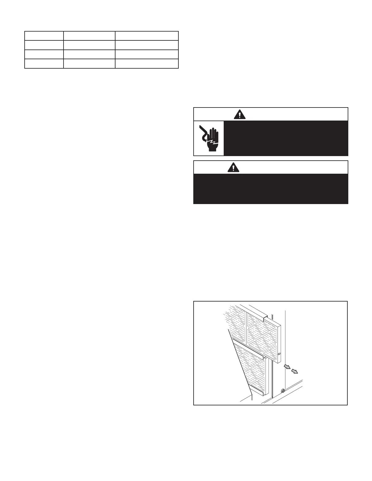
A-Filters
Refer to local codes or appropriate jurisdiction for ap-
NOTE-Filters must be U.L.C. certied or equivalent for
use in Canada.
B-Lubrication
All motors are lubricated at the factory. No further lubrica-
tion is required.
PULL TO
REMOVE
FILTERS
FIGURE 26

 Loading...

