When checking piping connection for gas leaks, use the
preferred means. Common kitchen detergents can cause
harmful corrosion on various metals used in gas piping.
The use of specialty Gas Leak Detector is strongly rec-
ommended.
Do not use matches, candles, ame or any other
source of ignition to check for gas leaks.
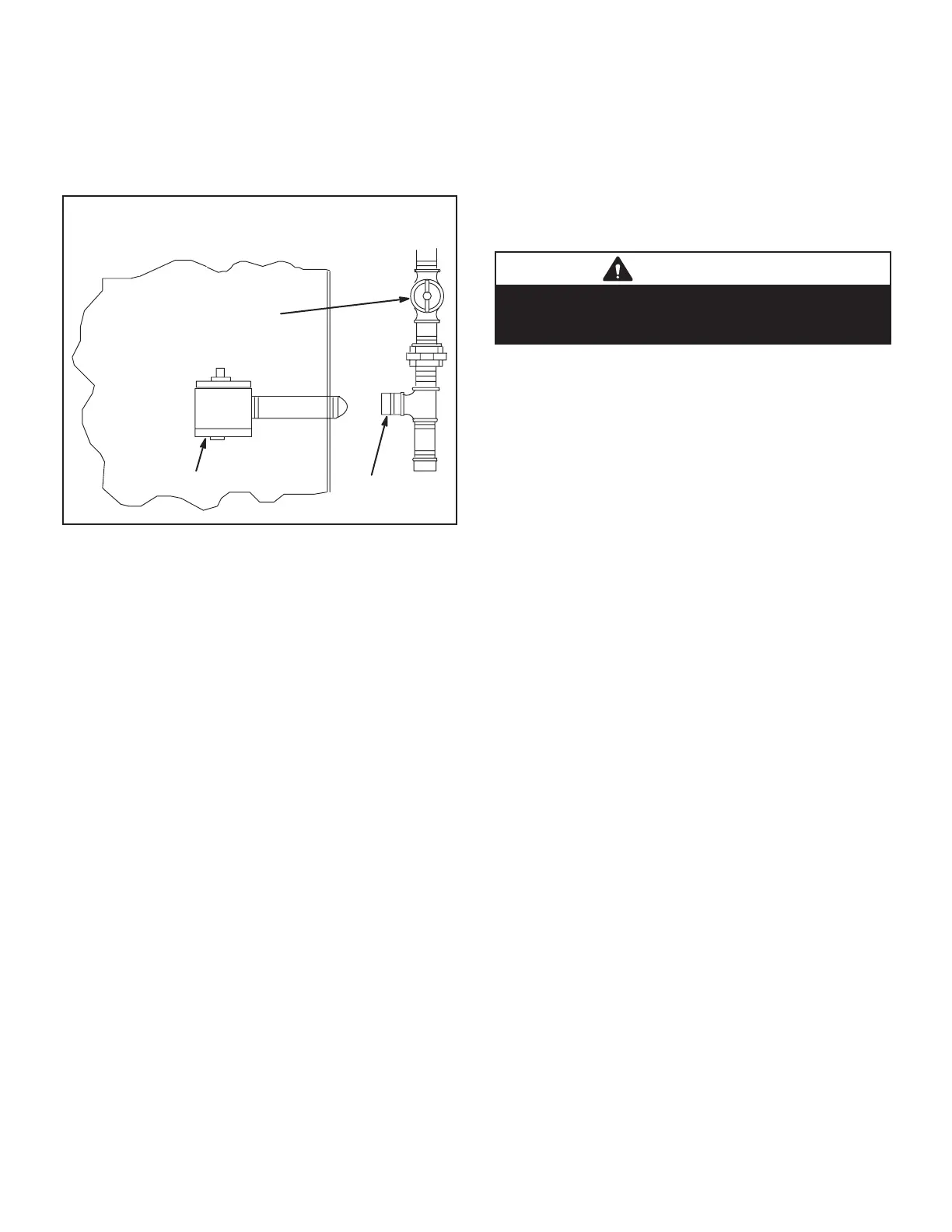
GAS VALVE
CAP
MANUAL MAIN
SHUT-OFF VALVE
PRESSURE TEST GAS LINE
FIGURE 25
3-Testing Gas Supply Pressure
When testing gas supply pressure, connect test gauge to
the inlet pressure tap located on unit gas valve GV1. Test
stages energized). Make sure the reading falls within the
range of the following values. Low pressure may result in
natural gas units, operating pressure at the unit gas con-
gas units, operating pressure at the unit gas connection
On multiple unit installations, each unit should be checked
separately while operating at maximum rate, beginning
with the one closest to the supply gas main and progress-
ing to the one furthest from the main. Multiple units should
also be tested with and without the other units operating.
Supply pressure must fall within the range listed in the
previous paragraph.
4-Check and Adjust Manifold Pressure
After line pressure has been checked and adjusted, check
manifold pressure. Move test gauge to the outlet pressure
-
tion of pressure tap on the gas valve.
The manifold pressure is factory set and should not re-
quire adjustment. See table 4. If manifold pressure is in-
correct and no other source of improper manifold pressure
for location of gas valve (manifold pressure) adjustment
screw.
All gas valves are factory regulated. The gas valve should
CAUTION
For safety, connect a shut-o valve between the
manometer and the gas tap to permit shut o of gas
pressure to the manometer.
Manifold Adjustment Procedure
1 - Connect test gauge to the outlet pressure tap on the
gas valve. Start the unit (call for second stage heat)
state.
2 - While waiting for the unit to stabilize, notice the
and should not lift from the burner heads. Natural
gas should burn basically blue with some clear
streaks. L.P. gas should burn mostly blue with some
clear yellow streaks.
3 -
record the manifold pressure and compare to the
values given in table 4. On two-stage units, check
before recording values.
Combustion gases
Flue products must be analyzed and compared to the unit
may make it necessary to temporarily shut down the fur-
nace until the items can be repaired or replaced.
5-Proper Gas Flow
-
-
tions of gas through the meter. (Two revolutions assures
a more accurate time.) Divide by two and compare to time
in table 11. Seconds in table 11 are based on a 1 ft.3. dial
ft3’ for LP. Adjust manifold pressure on gas valve to match
time needed.
NOTE - To obtain accurate reading, shut o all other gas
appliances connected to meter.

 Loading...

