Page 33
Turning O Gas to Unit
1 - If using an electromechanical thermostat, set to the
lowest setting.
2 -
power to the appliance.
3 - Open or remove the control access panel.
4 - Move gas valve switch(es) to OFF.
Close or replace the control access panel.
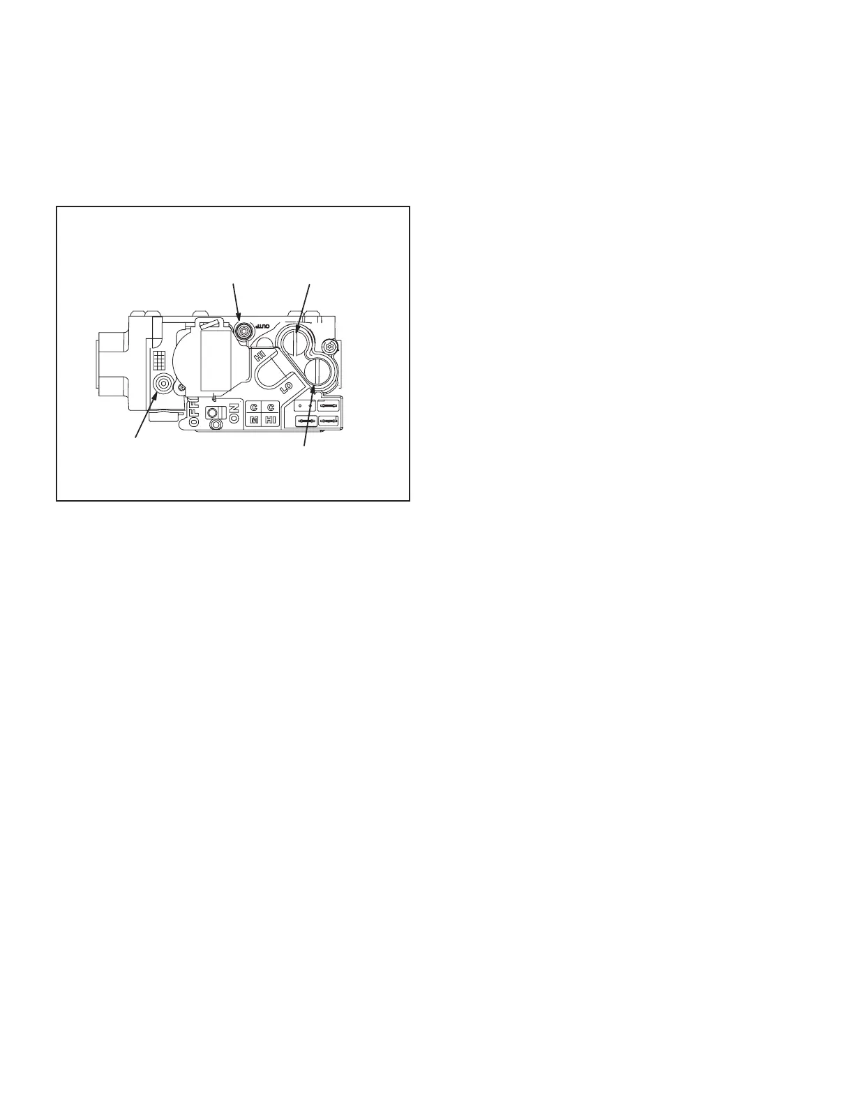
WHITE RODGERS 36J54 GAS VALVE
Two-Stage
Gas valve switch is shown in OFF position.
LOW FIRE
ADJUSTMENT
HIGH FIRE
ADJUSTMENT
INLET
PRESSURE
TAP
MANIFOLD
PRESSURE TAP
FIGURE 23
C-Cooling Start up
A-Operation
1 - Initiate full load cooling operation using the following
mobile service app menu path:
(COOL 4 on 074U units)
2 - Units contain one refrigerant circuit or stage.
3 - Unit is charged with R-410A refrigerant. See unit
rating plate for correct amount of charge.
4 - Refer to charging section method to check
refrigerant charge.
D-Safety or Emergency Shutdown
IV-CHARGING
A-Refrigerant Charge and Check - Fin/Tube Coil
WARNING-Do not exceed nameplate charge under
any condition.
This unit is factory charged and should require no further
adjustment. If the system requires additional refrigerant,
reclaim the charge, evacuate the system, and add re-
quired nameplate charge.
NOTE - System charging is not recommended below 60°F
(15°C). In temperatures below 60°F (15°C) , the charge
must be weighed into the system.
If weighing facilities are not available, or to check the
charge, use the following procedure:
1 - Attach gauge manifolds and operate unit in cooling
mode on HIGH SPEED with economizer disabled
Make sure outdoor air dampers are closed.
Note - Use mobile service app menu path SERVICE
> TEST > COOL > COOL 3 for 036, 048 and 060U
units. Use COOL 4 for 074U units.
2 - Use a thermometer to accurately measure the
outdoor ambient temperature.
3 - Apply the outdoor temperature to tables 6 through 9
to determine normal operating pressures. Pressures
4 - Compare the normal operating pressures to
the pressures obtained from the gauges. Minor
variations in these pressures may be expected due
could mean that the system is not properly charged
or that a problem exists with some component in
the system. Correct any system problems before
proceeding.
If discharge pressure is high, remove refrigerant
from the system. If discharge pressure is low, add
refrigerant to the system.
• Add or remove charge in increments.
• Allow the system to stabilize each time refrigerant is
added or removed.
6 -
methods along with the normal operating pressures
B-Subcooling Method - Ultra High Eciency Units
1 - Attach gauge manifold to the liquid line. With the
economizer disabled, operate the unit in cooling
mode at high speed using the following mobile
service app menu path:
(COOL 4 on 074U units)
2 - Use the liquid line pressure and a PT chart to
determin the saturated liquid temperature.
3 - Measure the liquid line temperature at the condenser
outlet.
Subcooling Temperature = Liquid Saturated Tempera-
ture Minus Liquid Temperature.
4 - The subcooling temperature should be as shown
this value indicates an overcharge. A subcooling
temperature less than this value indicates an
undercharge.

 Loading...

