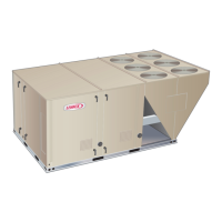
TWO-STAGE GAS HEAT SEQUENCE OF OPERATION
First Stage Heat:
1 - The thermostat initiates W1 heating demand.
2 - 24VAC is routed to controller A3. A3 proves N.C. primary limit S10..
3 - Control board A3 energizes combustion air inducer B6. After B6 has reached full speed, the combustion air blower
proving switch S18 contacts close.
4 -
Second Stage Heat:
6 -
7 -
8 - A3 energizes combustion air inducer B6 on high speed.
End of Second Stage Heat:
9 -
10 - Second stage heat is de-energized on GV1..
11 - Combustion air inducer B6 is now on low speed.
End of First Stage Heat:
12 -
13 - Ignition A3 is de-energized in turn de-energizing gas valve GV1 and combustion air inducer B6.
Optional Low Ambient Kit: (C.S.A. -50° C Low Ambient Kit)
14 - Line voltage is routed through the N.C. low ambient kit thermostats S60 and S61, to energize low ambient kit heater
HR6.

 Loading...